The term "stacking" applies to pressure compensators in two fundamentally different ways: physical assembly (modular valve sections bolted together) and functional circuit behavior (whether compensating effects accumulate in series or parallel paths). Both are valid engineering questions, but they demand separate answers. Understanding this distinction prevents costly design errors and ensures predictable multi-actuator performance.
TLDR
- Physical stacking via modular sandwich valves shares inlet/outlet galleries — it's a packaging method, not a hydraulic behavior
- In series, the higher-set compensator dominates; the downstream unit stays wide open and adds nothing
- Mismatched parallel compensators create priority bias, starving higher-load branches of flow
- Subsea volume compensators equalize housing pressure independently per device and don't interact in circuit logic
- Post-compensated valves prevent flow starvation when multiple actuators run simultaneously
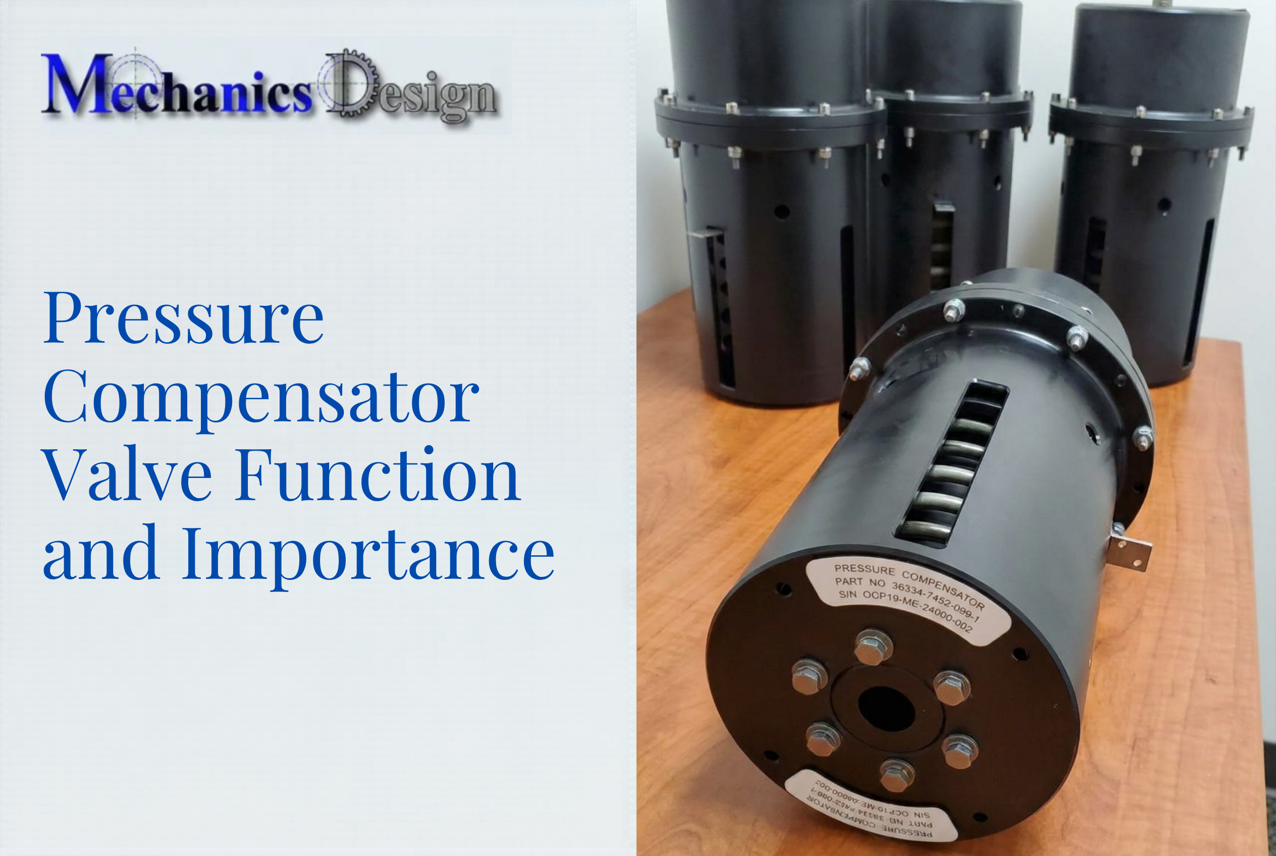
What Is a Pressure Compensator and What Does It Do?
A pressure compensator maintains a constant pressure differential (ΔP) across a flow control element regardless of upstream supply pressure or downstream load variations. This decouples flow rate from pressure fluctuations, ensuring consistent actuator speed even when system loads change dramatically.
Two distinct compensator types exist, and they behave very differently in practice:
Flow-control pressure compensators regulate actuator speed in load-sensing circuits. Per ISO 5598:2020, these valves maintain constant working flow rates by diverting surplus fluid when pressure differential exceeds the set point. Standard factory settings range from 3.5 bar (50 psi) to 15 bar (215 psi), with Parker's SPC series defaulting to 5 bar and Sun Hydraulics offering 50–200 psi options.
Volume compensators serve subsea and underwater equipment by equalizing internal fluid pressure with ambient external pressure. These devices use bladder, diaphragm, or piston interfaces to prevent seal failure and housing implosion at depth. The Seatools Basic Series rates this type of compensator to 3,000–5,000 meters for commercial ROV applications.
Confusion about whether compensators "stack" arises because the term covers both physical valve mounting methods and circuit behavior. Flow-control types regulate pressure differentials across valves; volume types equalize housing pressure against ambient depth. How each interacts in a system — and whether stacking applies — depends entirely on which type you're working with.
Two Ways "Stacking" Applies to Pressure Compensators
Physical Stacking: Modular Valve Assembly
In modular hydraulic systems, pressure compensator valve sections bolt directly to directional control valve bodies via standardized mounting interfaces—ISO 4401, NFPA D03/D05, and CETOP 3/5. These sandwich-style assemblies share common inlet and outlet galleries across the manifold, creating unified assemblies with fewer leak points and simplified external plumbing.
Physical stacking is purely a packaging decision. Bolting three compensator sections together in a vertical stack does not change how they interact hydraulically unless they are also connected in series or parallel fluid paths. The mechanical assembly and the circuit topology are independent variables.
Functional Series Stacking: Dominant Compensator Effect
When two pressure compensators sit in series along the same fluid path, each sees the pressure the other has already conditioned. The compensator with the higher differential pressure setting will dominate control. The downstream compensator becomes non-functional and stays fully open, because the upstream unit has already eliminated the pressure variation below its threshold.
Example: A 100 psi compensator followed by another 100 psi compensator does not yield 200 psi of combined regulation. The first compensator governs the flow; the second contributes only additional pressure drop without providing any additional regulation.
Understanding series behavior makes parallel stacking equally important to get right—because the failure mode is different and often harder to diagnose.
Functional Parallel Stacking: Flow-Sharing Challenge
Pressure compensators installed in parallel branches (each serving a separate actuator) independently regulate flow to their respective circuits. When both are set identically and the pump supplies sufficient flow, each performs as designed. Mismatched settings create priority bias—routing disproportionate flow to the lower-setting branch while starving the higher-setting branch.
Pre- vs. Post-Compensation at a Glance:
| Architecture | Compensator Location | Behavior Under Pump Saturation | Best Application |
|---|---|---|---|
| Pre-Compensated | Upstream of metering element | Flow prioritizes lowest-load actuator | Single-function operation |
| Post-Compensated | Downstream of metering element | Flow divides proportionally across all actuators | Simultaneous multi-actuator operation |
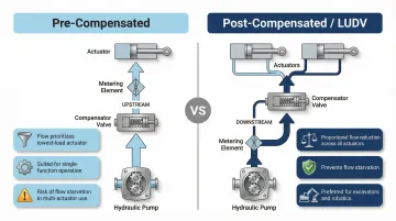
Post-compensated (LUDV) systems prevent flow starvation during simultaneous operation by ensuring all actuators slow down together at a fixed ratio when pump flow is exhausted. This proportional behavior is what makes LUDV the preferred architecture for excavators, multi-axis robotics, and ROV manipulator arms.
Series vs. Parallel: How Multiple Compensators Interact in a Circuit
Series Configuration: No Additive Regulation
Placing two flow-control compensators in series does not double the regulatory effect. The upstream compensator with the higher spring setting governs flow; the downstream unit stays wide open because upstream conditioning has already eliminated pressure variation.
Pressure drop losses, however, do accumulate. Each compensator contributes its differential setting to total system pressure loss, typically 3.5–15 bar per unit. A circuit with three 10 bar compensators in series adds 30 bar of cumulative pressure drop, which directly affects pump sizing and heat generation.
Parallel Configuration: Branch Starvation and Priority Conflicts
Series losses are manageable with proper pump sizing. Parallel circuits introduce a different problem. In multi-actuator systems where each branch has its own compensator, unmatched settings cause "fighting compensators" — the lower-set compensator prioritizes its branch, potentially starving the higher-set branch entirely when pump flow is insufficient.
Consider a pump delivering 15 gallons per minute (gpm) to two parallel circuits, each with a flow control set to 10 gpm. Flow takes the path of least resistance — 10 gpm flows through the valve with the lowest pressure, leaving only 5 gpm for the other branch instead of the equal 7.5 gpm split that proportional flow reduction would provide.
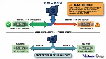
The fix is architectural: post-compensated designs with load sharing ensure proportional flow reduction across all channels when supply flow runs short.
Load-Sensing Signal Coordination
In load-sensing pump circuits, the LS signal reports the highest load pressure back to the pump. Multiple compensators interact with this signal — each must see enough differential to regulate. Factory LS margin settings typically default to 10–15 bar for Parker PV pumps.
The pump LS margin must be set slightly above the maximum valve compensator differential. If the margin falls too low to cover the highest-load compensator's requirement, the whole system loses flow regulation and actuators become sluggish or unresponsive.
Special Considerations for Underwater and Subsea Hydraulic Systems
Volume Compensators Equalize Housing Pressure
In underwater and subsea applications, "pressure compensator" almost always refers to a housing or volume compensator—a fluid-filled bladder or piston that equalizes internal pressure with external ambient water pressure. These devices prevent seal inversion and structural collapse at depth by maintaining a slight positive bias (0.7–1.0 bar above ambient).
Subsea compensators do not interact with each other in a circuit the way flow-control compensators do. Each device (motor, actuator, electronic housing) has its own compensator managing its own internal pressure. In short, subsea compensation is a device-level function, not a circuit-level one.
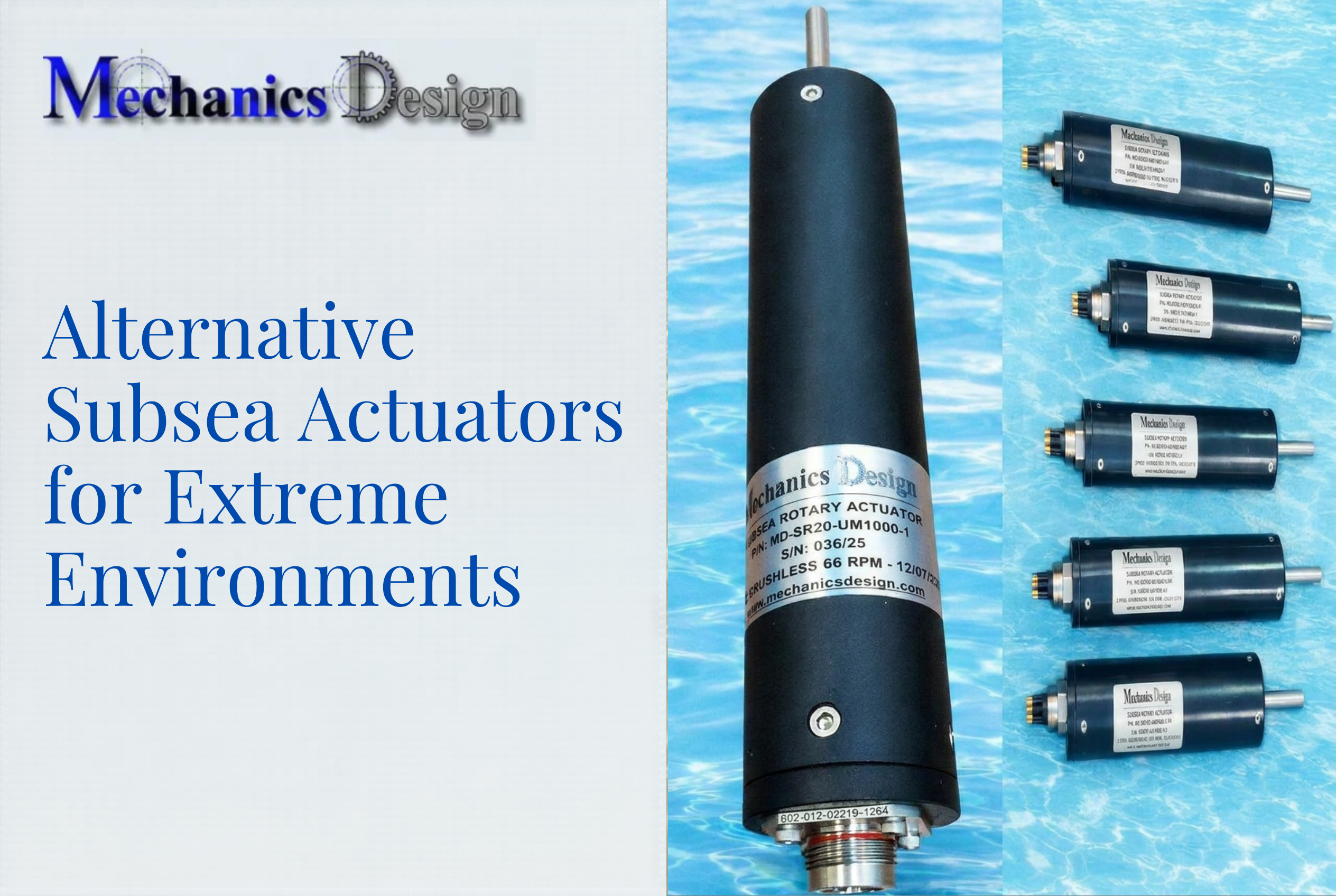
Self-Contained Pressure Compensation in ROV Actuators
For hydraulically-driven underwater robotics with multiple pressure-compensated actuators, the challenge is not compensator interaction but ensuring each actuator's compensation volume accommodates thermal expansion and contraction cycles at depth.
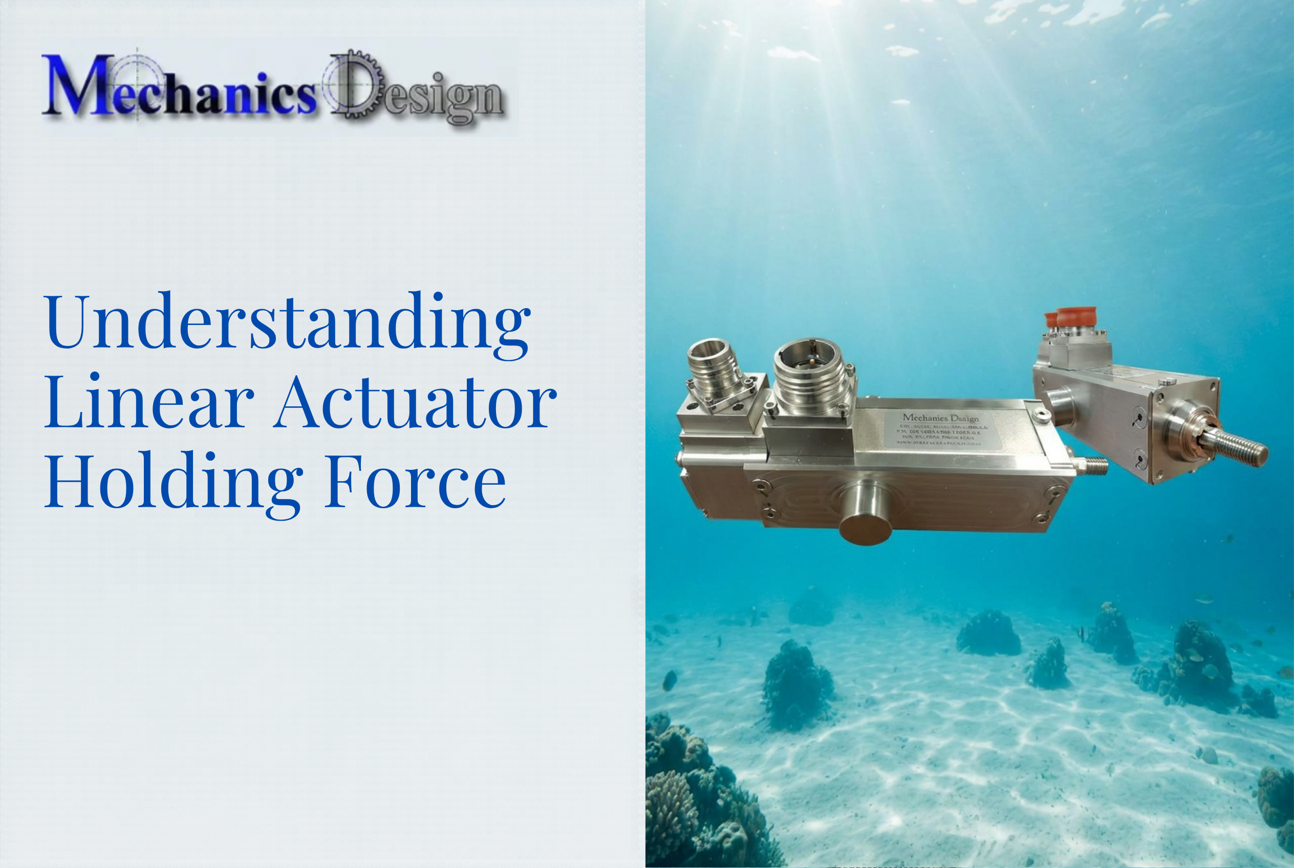
Self-compensated actuator designs address this by isolating all compensation management inside the housing itself. Key characteristics of this approach include:
- All compensation circuitry contained within the actuator housing
- Depth ratings from 3,000 to 6,000 meters without external compensation circuits
- No separate compensator sizing or volume calculations required per device
- Simplified system integration across multi-actuator ROV platforms
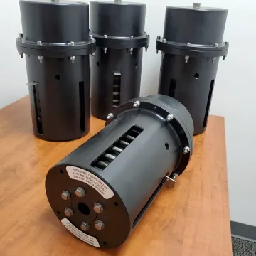
NV Mechanics Design Ltd. builds electric actuators along these lines, with integrated pressure compensation that removes the design burden from system integrators entirely.
Key advantage: System designers specify electric actuators with integrated pressure compensation rather than managing external compensator sizing, circuit routing, and volume calculations across multiple devices.
Design Best Practices When Using Multiple Pressure Compensators
Match Compensator Settings in Parallel Circuits
Use identical compensator differential settings across parallel branches whenever simultaneous equal-speed operation is required. If intentional priority is needed (e.g., steering priority over implement functions), size the priority branch compensator lower and document this as a design decision.
Choose Architecture Based on Application Requirements
Pre-compensated systems give flow priority to the lowest-loaded actuator—acceptable for single-function operation where only one actuator moves at a time.
Post-compensated systems proportionally reduce all actuator speeds when pump flow is insufficient—strongly preferred for multi-function simultaneous operation such as excavators and material handlers.
Account for Cumulative Pressure Drop in Pump Sizing
Your architecture choice directly affects how much pressure headroom the pump must supply. Calculate total expected pressure drop by summing the differential settings of all in-series compensators, then add static head and line losses when determining minimum pump output pressure.
Example calculation: A circuit with three 10 bar compensators in series, 5 bar of line losses, and a 50 bar actuator load requires a minimum pump output pressure of:
- 30 bar (compensator drops) + 5 bar (line losses) + 50 bar (load) = 85 bar minimum
Undersizing the pump by ignoring cumulative compensator drops causes:
- Sluggish actuator response under load
- Overheating from pressure relief cycling
- Premature component wear across the circuit
Frequently Asked Questions
What is the purpose of a pressure compensator?
A pressure compensator maintains a constant pressure differential across a flow control element, keeping actuator speed steady regardless of load or supply pressure fluctuations. In subsea applications, it equalizes internal housing pressure with ambient water pressure to protect seals and prevent structural damage at depth.
How does a subsea compensator work?
A subsea compensator uses a sealed, oil-filled bladder or piston that expands or contracts as depth changes. This matches internal pressure to external water pressure, preventing seal failure, water ingress, and housing implosion at operating depth.
When would pressure compensation be required for flow control?
Pressure compensation is required when consistent actuator speed must be maintained despite varying load pressures. This is common in multi-function hydraulic machinery, load-sensing systems, and circuits where two or more actuators share a single pump.
Can two pressure compensators be placed in series in a hydraulic circuit?
While physically possible, placing two flow-control compensators in series is seldom justified in practice. The upstream compensator with the higher set point governs flow, leaving the downstream one fully open and non-functional. This configuration adds unnecessary pressure drop without providing additional regulation.
Do pressure compensator pressure drops add up when multiple are used?
Compensator set points do not "stack" to provide more regulation, but pressure drop losses do accumulate. Each compensator in series contributes its own differential drop to total circuit pressure loss, which must be accounted for during pump selection and system sizing.