Introduction
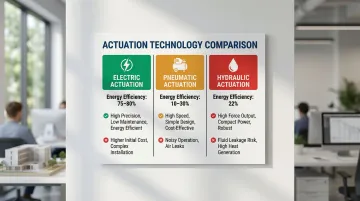
Electric actuators convert electrical energy into controlled mechanical motion—either linear or rotational—and their use is accelerating across automation, robotics, and industrial systems. According to energy efficiency research, they operate at 75-80% efficiency, compared to 22% for hydraulic systems and 10-30% for pneumatic alternatives.
That efficiency advantage only holds when you select the right type. Distinct actuator categories exist for different motion requirements, load profiles, and operating environments. Mismatches cause motor strain, accelerated wear, and avoidable failures.
This guide breaks down the four primary categories—linear, rotary, multi-turn, and quarter-turn—so you can match each type to the application it was designed for.
TL;DR
- Electric actuators convert electrical energy into mechanical motion using motors and transmission mechanisms
- Four primary types exist: linear (push/pull), rotary (angular rotation), multi-turn (multiple revolutions), and quarter-turn (90-degree travel)
- Selection depends on motion type, force/torque requirements, environmental conditions, and control integration needs
- Compared to pneumatic and hydraulic alternatives, electric actuators offer superior precision, lower energy consumption, and reduced maintenance
- Pressure-compensated designs extend operation into extreme subsea environments — rated to depths of 3,000–6,000 meters
What Is an Electric Actuator?
An electric actuator is a device powered by electricity (AC or DC) that drives a motor to produce controlled mechanical movement—either in a straight line or along a rotational arc. Unlike manual systems or passive mechanisms, electric actuators deliver repeatable, programmable motion under electronic control.
Core components include:
- Power source – AC or DC electrical supply
- Motor – Converts electrical energy to rotational motion (brushed DC, brushless DC, or AC induction)
- Controller/drive – Manages motor speed, direction, and position
- Transmission mechanism – Lead screw, ball screw, gear train, or belt drive converts that rotation into useful output
- Feedback sensor – Encoder, potentiometer, or limit switch that reports position back to the controller
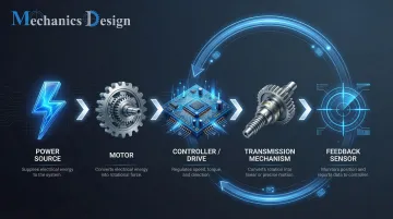
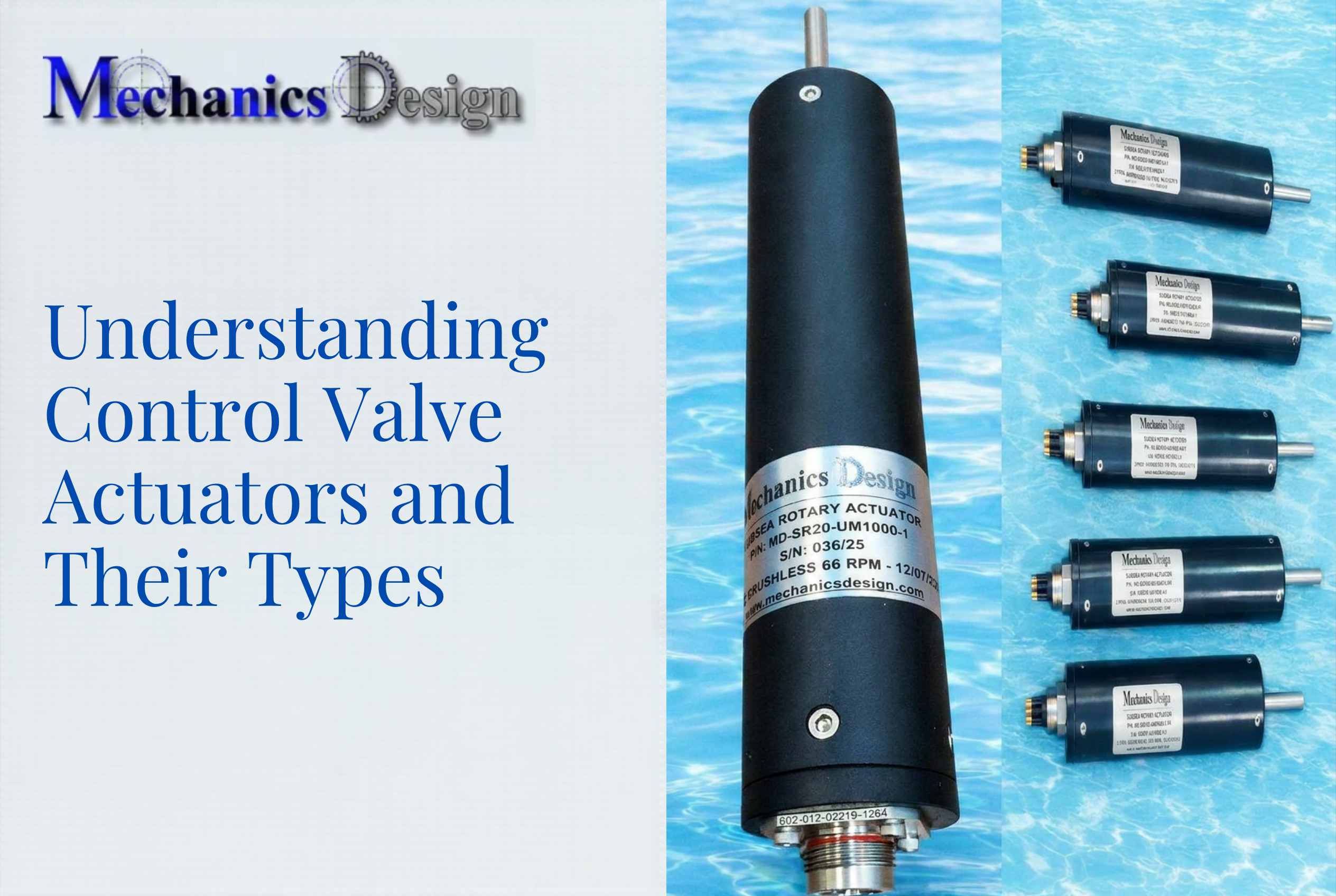
Together, these components form a closed-loop system capable of operating across a wide range of environments and loads. In practice, electric actuators appear in industrial valve control systems, robotic manipulators, medical equipment, HVAC damper drives, and underwater inspection robots. NV Mechanics Design, for example, manufactures pressure-compensated electric actuators rated to 3,000–6,000 meters water depth for subsea robotics — a range that would destroy most standard actuator designs.
Types of Electric Actuators
Electric actuators are not a single-category product. The right type depends on the direction of motion needed, the force or torque involved, and the deployment environment — including whether the application is above ground or operating under significant water pressure.
The four main types covered here — linear, rotary, multi-turn, and quarter-turn — each solve different motion problems. Understanding where they differ helps narrow selection before getting into sizing and specifications.
Linear Electric Actuators
A linear electric actuator converts the rotary motion of an electric motor into straight-line push or pull force. This conversion occurs through a lead screw, ball screw, or roller screw mechanism, producing precise back-and-forth motion along a fixed axis.
Three screw mechanisms are common, each with different efficiency and load trade-offs:
- Lead screws – Compact and self-locking, but lower efficiency due to sliding friction
- Ball screws – Use recirculating ball bearings to achieve approximately 80% efficiency
- Roller screws – Multiple threaded rollers provide the highest dynamic load rating, achieving forces up to 178 kN
Best suited for: valve positioning, robotic arm extensions, automated lifting, pressing tasks, and underwater manipulation. Rod-style variants (enclosed, high IP-rated) handle harsh and subsea environments well; rodless designs suit space-constrained installations where a compact footprint matters.
Strengths:
- Precise positional control down to sub-millimeter accuracy
- Quiet operation compared to hydraulic cylinders
- Draws power only when moving, not while holding position
- Mechanical locking holds position without continuous power draw
One notable trade-off: higher thrust output typically means lower travel speed. Stroke length is also capped — generally up to a few meters — and these actuators produce no rotational output.
Rotary Electric Actuators
Rotary electric actuators produce angular motion around a fixed axis. An electric motor connects to a gear mechanism — worm, planetary, or bevel gear — or a direct-drive coupling, enabling continuous or defined-angle rotation of an output shaft.
Best suited for: robotic joints, conveyor indexing, damper control, and valve automation where rotation extends beyond 90 degrees or a fixed number of turns. They excel at precise angle control across multiple revolutions — a use case where linear actuators simply don't apply.
Strengths:
- Angular positioning precision often better than 0.1 degrees
- Compact relative to torque output
- Integrates with PLCs and control systems via RS232, Modbus, or encoder feedback — including in subsea deployments where tether-based RS232 control is common
The main limitations: no linear displacement capability, torque output falls short of hydraulic alternatives in extreme heavy-duty scenarios, and high gear ratios reduce back-drivability even as they improve holding torque.
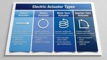
Multi-turn Electric Actuators
Multi-turn actuators deliver multiple full rotations of the output shaft via a worm gear or spur gear train driven by an electric motor. ISO 22153 defines them as actuators transmitting torque across at least one full revolution while handling both torque and axial thrust loads.
Best suited for: rising stem gate valves, globe valves, and sluice gates in water treatment, oil and gas pipeline management, and power generation — anywhere the valve travels through many turns from fully open to fully closed. The Flowserve Limitorque SMB series illustrates the torque range available: 20 Nm to 81,349 Nm.
Strengths:
- High torque output suited to heavy-duty valve applications
- Self-locking worm gears (lead angles below 5°) prevent back-drive without power
- Precise position control maintained across multiple revolutions
- Standardized mounting per ISO 5210
The trade-offs are size and speed. Multi-turn actuators are bulkier and slower than quarter-turn alternatives, and the additional gear complexity adds cost at high-torque configurations. They're not the right choice where rapid on/off actuation is the primary requirement.
Quarter-turn Electric Actuators
Quarter-turn actuators rotate an output shaft exactly 90 degrees — open to closed — using a worm gear mechanism driven by an electric motor. They're purpose-built for on/off valve applications, with no adjustability for intermediate positions.
Best suited for: ball valves, butterfly valves, and plug valves in water treatment, HVAC, chemical processing, and oil and gas — wherever rapid, repeatable open/close cycles are needed. The Bray Series 76 delivers up to 9,000 Nm torque with 90-degree travel times between 17 and 130 seconds depending on configuration.
Strengths:
- Fast cycle speeds suited to high-frequency open/close applications
- Compact form factor relative to torque output
- Repeatable across thousands of cycles with minimal drift
- Straightforward mounting on standard valve configurations per ISO 5211
The 90-degree travel limit is also its main constraint. Quarter-turn actuators don't support proportional control, multi-position regulation, or continuous rotation — for those applications, a rotary or multi-turn actuator is the correct choice.
Electric Actuators vs. Other Actuation Technologies
Electric vs. Pneumatic
Pneumatic actuators offer faster cycle speeds and simpler construction but require compressed air infrastructure. They produce less precise positioning and operate at 10-30% energy efficiency compared to 75-80% for electric systems. In a 0.5 kW application operating at 80% duty cycle, annual electricity costs for pneumatic cylinders exceed CAD $1,400 versus CAD $350 for electric actuators. Electric actuators are preferred where compressed air is unavailable or where precision and low maintenance are priorities.
Electric vs. Hydraulic
Hydraulic systems deliver superior raw force output and are better suited for the heaviest loads. However, they introduce risks of fluid leakage, require additional infrastructure (reservoirs, pumps, hoses), and operate at approximately 22% energy efficiency—far below electric alternatives.
Hydraulic fluid leaks pose environmental contamination risks, particularly in subsea and offshore environments. Electric actuators offer cleaner operation, more controllable performance, and lower maintenance for most precision automation contexts.
Choosing the Right Technology
No single actuation type wins across all applications. The right choice depends on force requirements, environment, and infrastructure:
- Pneumatic: Best for extremely high-speed, low-precision tasks where compressed air infrastructure already exists
- Hydraulic: Appropriate for ultra-heavy-duty loads beyond electric force capabilities — though that gap is closing, with modern electric actuators now reaching up to 178 kN
- Electric: The default choice for precision automation, clean environments, and applications where controllability and low maintenance matter most
How to Choose the Right Electric Actuator
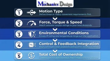
Getting the selection right comes down to five criteria, evaluated in order of impact:
1. Motion type — Does the application need linear motion (push/pull along an axis) or rotational motion (angular movement around a shaft)? This single question narrows the field before anything else is considered.
2. Force, torque, and speed — Calculate required output force (linear) or torque (rotary/multi-turn/quarter-turn) based on actual load conditions. Under-specifying causes motor strain and failure; over-specifying adds unnecessary cost and bulk. Keep in mind: within a given actuator class, higher thrust typically means lower speed.
3. Environmental and operating conditions — This factor is critical and often underweighted. Consider:
- Temperature range (motors and electronics have thermal limits)
- IP rating against moisture and dust (IP66 or IP68 for harsh environments)
- Exposure to corrosive substances
- Pressure-rated requirements for submerged applications
For subsea applications, NV Mechanics Design Ltd. produces pressure-compensated electric actuators rated to 3,000–6,000 meters water depth, with self-contained circuitry, oil-filled pressure-balanced designs, and stainless steel 316 or titanium construction.
4. Control and feedback integration — The actuator must be compatible with your system's control architecture, whether that's simple on/off signals, 4–20mA analog input, or digital feedback loops requiring position data. Absolute encoders (which retain position data between power cycles) are essential where power interruptions cannot be tolerated, such as emergency shutdown valves.
5. Total cost of ownership — Account for installation complexity, maintenance requirements, energy consumption, and service life. Electric actuators typically cost less over their lifetime than hydraulic alternatives, despite a higher upfront price, because they consume less energy and have fewer components requiring regular service.
Common Mistakes to Avoid When Selecting an Electric Actuator
Three mistakes account for the majority of poor actuator selections:
Over-specifying the actuator type. Using a multi-turn actuator with absolute encoder feedback for a basic on/off ball valve application adds cost and complexity with no operational benefit. Match capabilities to what the application actually requires — nothing more.
Ignoring environmental ratings. Choosing based on performance specs alone, without confirming IP rating, operating temperature range, and material compatibility, leads to premature failure. Saltwater, chemical exposure, and temperature extremes require actuators built specifically for those conditions.
Defaulting to a familiar type. An actuator that worked well in one application isn't automatically the right fit for the next. Each deployment needs independent evaluation against motion type, load, environment, and control integration requirements.
Conclusion
Electric actuators exist in distinct types—linear, rotary, multi-turn, and quarter-turn—each engineered to perform a specific kind of motion under specific conditions. Understanding these differences is the foundation of reliable actuation system design. Each type maps to a defined mechanical function: linear for extension and retraction, rotary for angular positioning, multi-turn for rising-stem valve control, and quarter-turn for fast 90-degree switching.
The right choice comes down to matching the actuator's motion profile to your application's specific requirements—operating environment, control interface, duty cycle, and total lifecycle cost. Getting this decision right at the specification stage prevents failures, reduces maintenance demands, and improves overall system performance.
Electric actuators offer superior efficiency, precision, and environmental cleanliness compared to pneumatic and hydraulic alternatives. In demanding environments—including subsea operations where hydraulic fluid leaks are unacceptable and pressure compensation is non-negotiable—this matters more than any other factor. Selecting the correct actuator type from the outset is what keeps systems running reliably at depth, under pressure, and without unplanned intervention.
Frequently Asked Questions
What is an electric actuator?
An electric actuator is a device that converts electrical energy into controlled mechanical motion—either linear or rotary—using a motor and a transmission mechanism such as a lead screw or gear train. It is used wherever automated, precise movement is needed in industrial, commercial, or scientific systems.
What are the different types of electric actuators?
The four primary types are linear (push/pull straight-line motion), rotary (angular rotation around an axis), multi-turn (multiple full revolutions for rising-stem valves), and quarter-turn (90-degree travel for ball and butterfly valves). Each type is designed for a specific direction and range of motion.
What are electric actuators used for?
Electric actuators are deployed across industrial valve control, robotics, medical equipment, HVAC systems, water treatment infrastructure, automotive systems, and underwater inspection equipment.
How much does an actuator cost?
Electric actuator pricing varies widely based on type, torque/force rating, environmental protection level, and integrated features. Basic linear actuators start around CA$1,000–2,000, while high-spec industrial multi-turn models can exceed CA$10,000. Specialized subsea-rated actuators range from CA$5,000 to CA$12,000 depending on depth rating and force capacity.
What is another name for an actuator?
Actuators are sometimes called drives, movers, or motion devices in general engineering contexts. Specific configurations may be called linear drives, servo actuators, or electric operators depending on the industry and application.
Can electric actuators be used in harsh or underwater environments?
Yes. Specialized electric actuators are engineered for extreme environments through high-IP-rated enclosures (IP66, IP68) for moisture and dust resistance. Pressure-compensated, oil-filled designs rated to 6,000 meters deep are used in subsea robotics, offshore oil and gas, and underwater inspection applications.