Introduction
Underwater industrial operations—from offshore energy production to municipal water tank inspection and industrial cooling systems—rely on specialized components to function remotely and reliably in environments hostile to conventional machinery. At the heart of these operations are subsea actuators: electromechanical devices that convert energy into motion to operate valves, robotic arms, and other submerged equipment.
Standard actuators simply aren't built for what's down there. Hydrostatic pressure crushes housings at depth, saltwater corrosion destroys electrical components, and routine maintenance is often impossible. This article covers what subsea actuators are, how they differ by type, what engineering obstacles they overcome, and how to select the right one for your application.
While traditionally associated with offshore oil and gas, subsea actuator technology is increasingly critical in water management, environmental inspection, and industrial cleaning robotics—applications where eliminating human entry into hazardous submerged environments can save both lives and operational costs.
TLDR:
- Subsea actuators drive underwater valves, arms, and tools—engineered for extreme pressure, corrosion, and remote operation
- Three main types: hydraulic (reliable but infrastructure-heavy), electric (simpler systems), and hybrid (combines both)
- Pressure compensation systems balance internal actuator pressure with external seawater pressure, preventing implosion without impractical wall thickness
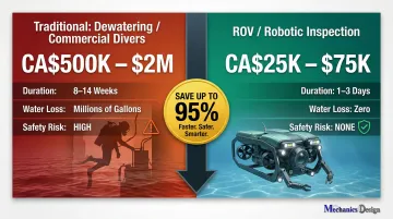
- ROV-based systems now cut municipal water infrastructure inspection costs from CA$500,000+ down to CA$25,000–$75,000
- Selection criteria include depth rating, motion type, failsafe design, and control interface compatibility
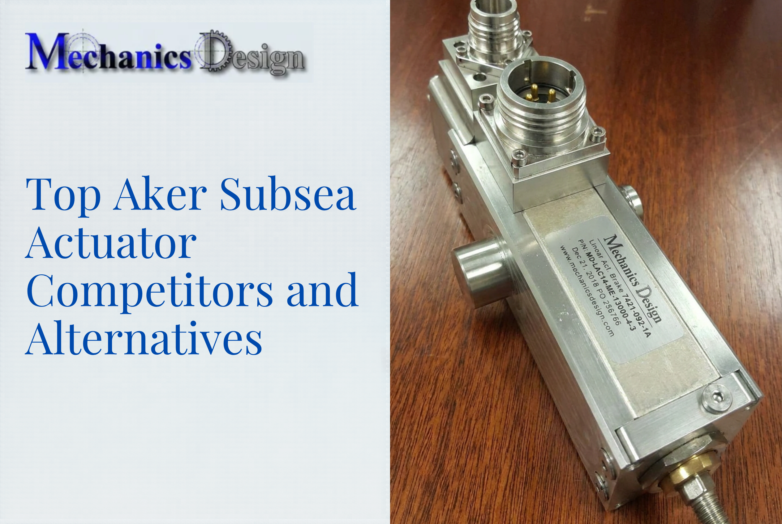
What Is a Subsea Actuator?
A subsea actuator is a machine component that converts energy—hydraulic, pneumatic, or electric—into mechanical motion to operate valves, robotic manipulators, or other equipment deployed underwater. Unlike standard industrial actuators, subsea designs are purpose-built to withstand underwater pressure, resist corrosion, and enable remote operation from surface control systems.
Where They're Deployed:
Subsea actuators appear in diverse underwater environments:
- Oil and gas infrastructure: Christmas trees (the assembly of valves controlling well production per API 6A/ISO 10423) and subsea manifolds
- Remotely operated vehicles (ROVs): Manipulator arms and tool systems
- Municipal water systems: Drinking water reservoirs, wastewater treatment tanks, stormwater management chambers
- Industrial facilities: Cooling tower inspection robots, process water tanks, environmental monitoring equipment
Across all these environments, the actuator is the component that determines whether the system performs reliably or fails. A well-designed valve or mechanism will underperform if its actuator cannot deliver consistent force and precise control in deep or chemically aggressive conditions.
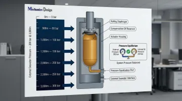
The pressure challenge is significant. According to NOAA data, pressure increases by approximately 1 bar (14.7 psi) every 10 meters of depth—at 3,000 meters, equipment faces roughly 300 bar of external force. Standard industrial actuators designed for atmospheric pressure simply cannot function at that depth.
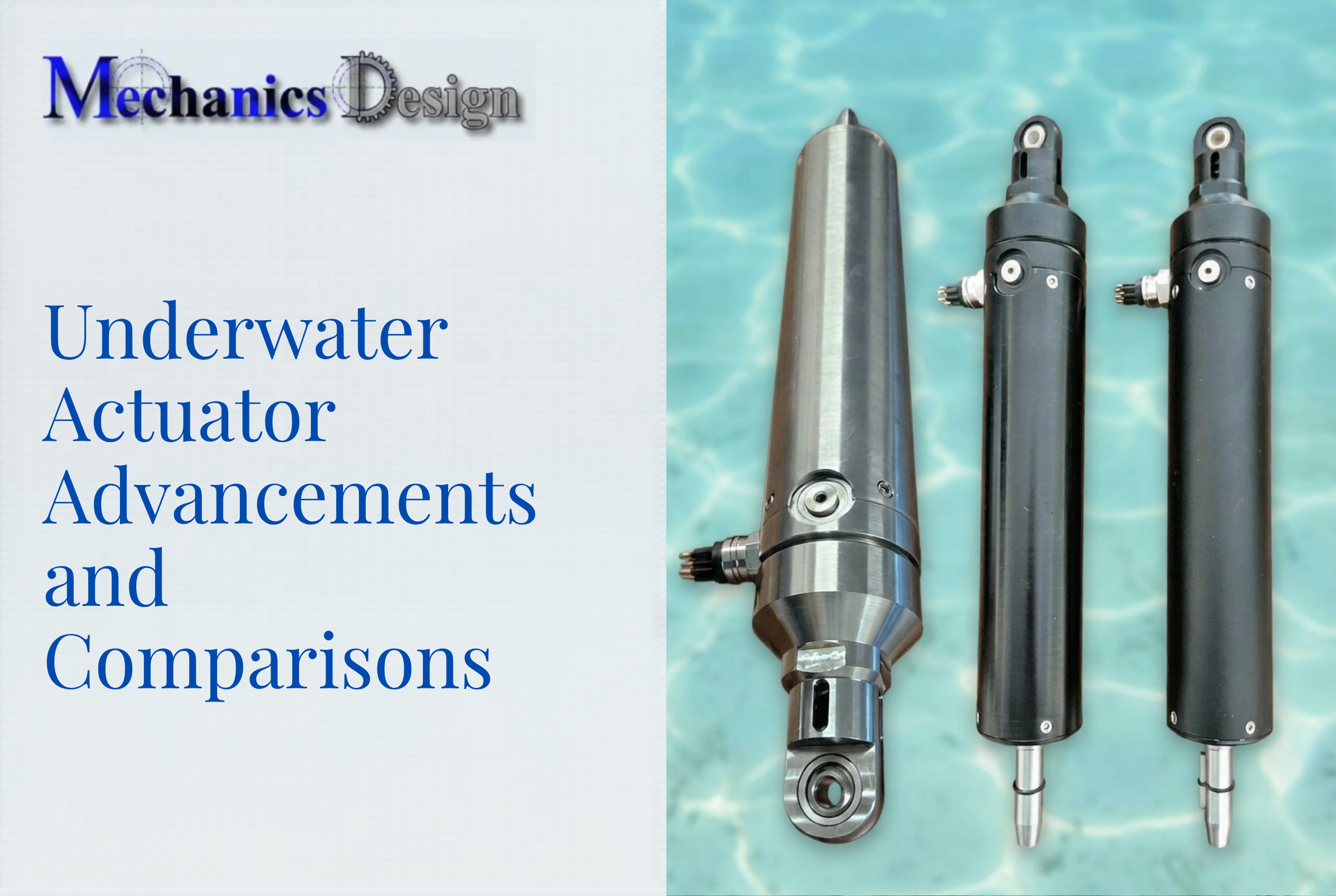
Types of Subsea Actuators
Energy Categories and Mechanism Types
Three main energy sources power subsea actuators: hydraulic, electric, and hybrid (electro-hydraulic). Pneumatic actuators—common in surface applications—are impractical for subsea work due to gas compressibility. Research published in PMC shows that gas compressibility (1.4 × 10⁶ Pa) is three orders of magnitude greater than hydraulic oil (1.7 × 10⁹ Pa), resulting in spongy control and severe leak risks at depth.
Actuator Mechanisms:
| Mechanism Type | Motion Output | Typical Application | Torque Profile |
|---|---|---|---|
| Linear | Straight-line push/pull | Gate valves, positioning systems | Direct thrust force |
| Scotch Yoke | 90-degree rotation | Ball and butterfly valves | Higher at stroke ends |
| Rack-and-Pinion | 90-degree rotation | Throttling, precise positioning | Constant throughout stroke |
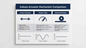
Linear actuators produce straight-line motion for gate valves and positioning tasks. They typically operate as spring-return designs with fail-safe closed functionality, which is critical when power loss must default the system to a safe state.
Scotch yoke and rack-and-pinion rotary actuators both provide quarter-turn motion for ball valves through different mechanics. Scotch yoke designs convert linear piston movement to rotational torque via a yoke-and-pin mechanism, delivering non-linear torque that peaks at the beginning and end of the stroke.
Rack-and-pinion actuators use meshing linear and rotary gears, providing constant torque throughout the rotation. That consistency makes them better suited for throttling and precise positioning applications.
These mechanism differences matter most when selecting actuators by energy source. Each energy category carries distinct infrastructure requirements, environmental tradeoffs, and diagnostic capabilities.
Hydraulic Subsea Actuators
Hydraulic actuators function using pressurized fluid supplied via umbilical lines from surface Hydraulic Power Units (HPUs). They hold a 49% market share valued at CAD $1.22 billion in 2025.
Advantages:
- Field-proven reliability over 50+ years
- High force density in compact packages
- Mechanical spring failsafe capability (SIL 3 rated)
Limitations:
- Require kilometer-long umbilical lines carrying hundreds of liters of hydraulic fluid
- Environmental spill risk — BSEE Safety Alert 419 documented a failed seal that leaked 3–50 barrels of hydraulic fluid and hydrocarbons into the Gulf of Mexico
- Complex topside HPU infrastructure
- Limited real-time diagnostics compared to modern electric systems
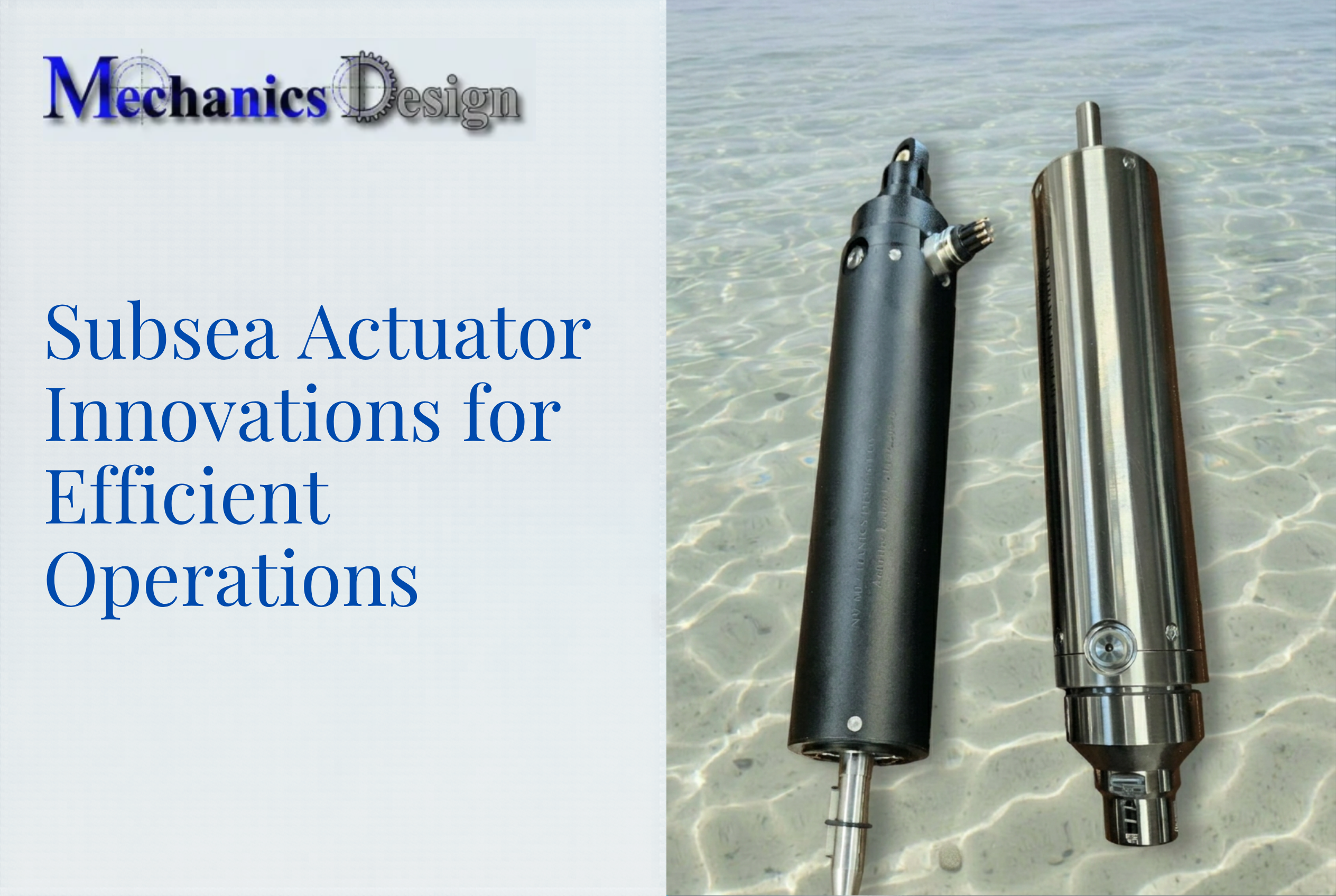
Electric Subsea Actuators
Electric actuators receive power via cables and communicate through Actuator Control Modules (ACMs). Representing 18% market share (CAD $450 million), they're projected to show the strongest growth through 2034 as operators eliminate hydraulic leak paths.
Advantages:
- Simplified infrastructure (power cable and data line only, no hydraulic umbilicals)
- Reduced environmental spill risk
- Precise motion control with encoder feedback
- Built-in condition monitoring via integrated sensors
Traditional Disadvantages:
- Lower power density requiring larger housings
- Mechanical wear in gearboxes and drive components
- Battery dependency for failsafe operation (batteries degrade over time)
- Higher peak energy consumption in electromechanical designs
Recent electric designs have closed most of these gaps. NV Mechanics' self-compensated actuators, for instance, include all driver and logic circuitry internally with 30-bit absolute encoders that retain position information between power cycles, eliminating external control modules and reference systems while maintaining precision to 0.1 degrees.
Key Engineering Challenges for Subsea Actuators
Hydrostatic Pressure
The primary design challenge is pressure. NOAA confirms that every 10 meters of water depth adds roughly 1 atmosphere (1 bar or 14.5 psi). At operational depths of 3,000 meters—common for deepwater oil and gas operations—equipment endures roughly 300 bar (4,351 psi) of external seawater pressure.
Uncompensated housings would require impractically thick walls to resist this force, adding prohibitive weight and cost.
Pressure Compensation Solution:
Engineers solve this with pressure compensation systems: a sealed compensator capsule filled with pressurized oil (nearly equal to ambient seawater pressure) connects to the actuator housing. This balances internal and external pressure, preventing implosion without requiring fortress-thick walls.
NV Mechanics' actuators, for instance, use oil-pressure compensation rated to 3,000 meters depth, with all circuitry self-contained within the housing. This eliminates the need for separate external pressure vessels. The company's 260cc oil compensators employ rolling diaphragm designs that maintain 0.7–1 bar positive internal pressure across the full volume, preventing seawater ingress. Visual oil level monitoring is available through slots in the spring housing.
Corrosion and Sealing
Saltwater aggressively corrodes metals and electrical components. Subsea actuators require:
- Corrosion-resistant materials: Duplex stainless steels (e.g., UNS S32750 per NACE MR0175/ISO 15156), titanium, or Inconel alloys
- Subsea-rated connectors: Seacon underwater connectors or equivalent with proven seal performance
- Component protection: All electronics not inherently subsea-rated must be encapsulated or mechanically shielded
Materials selection follows strict standards. DNV-RP-F112 provides recommended practices for duplex stainless steel designs to mitigate hydrogen-induced stress cracking (HISC) in cathodically protected subsea equipment.
Failsafe and Safety Requirements
Where human intervention is impossible or dangerous, actuators must default to a safe position upon power failure. Typical configurations use mechanical spring-based systems that drive the valve to a closed (or open) position when control power is lost.
These failsafe systems are evaluated against Safety Integrity Level (SIL) standards per IEC 61508 and IEC 61511. Actuators serving as Emergency Shutdown (ESD) devices or Underwater Safety Valves typically require SIL 2 or SIL 3 certification, demonstrating statistically reliable performance in safety-critical functions.
Maintenance and Operational Lifespan
Subsea equipment operates for extended periods with minimal maintenance access. IOGP JIP33 S-561 mandates that subsea tree systems be designed for a 25-year operational life, including pre-production wet storage and post-production phases.
Meeting this requirement demands:
- Redundant drive components
- Condition monitoring via built-in sensors broadcasting operational status
- Designs minimizing mechanical wear (brushless motors, sealed bearings)
- Materials resistant to long-term environmental degradation
Electric and hybrid designs continuously record operating states and report to master controllers via serial communication protocols (RS422/RS232), enabling trend analysis and early detection of deviations.
Hydraulic vs. Electric vs. Hybrid: Choosing the Right Subsea Actuator
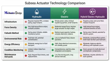
| Factor | Hydraulic | Electric (Traditional) | Hybrid Electro-Hydraulic |
|---|---|---|---|
| Infrastructure | Topside HPU + km-long umbilical lines | Power cable + data line only | Power cable + data line only |
| Force Density | Excellent (compact for high force) | Lower (larger housings needed) | Excellent (internal hydraulics) |
| Failsafe Method | Mechanical spring (SIL 3 proven) | Battery backup (degrades over time) | Mechanical spring (no battery) |
| Environmental Risk | High (hydraulic fluid spill potential) | Low (no fluid leaks) | Very low (closed internal circuit) |
| Energy Efficiency | Moderate | Variable (higher peak consumption) | High (up to 75% savings claimed) |
| Condition Monitoring | Limited real-time diagnostics | Extensive built-in sensors | Extensive built-in sensors |
| Maintenance Demands | HPU servicing, umbilical inspection | Mechanical wear in gearboxes | Reduced wear, self-contained |
Hydraulic Trade-offs
Hydraulic systems deliver high force output with field-proven reliability spanning decades. Mechanical spring failsafes provide SIL 3-rated safety performance without electronic dependency. However, they require extensive topside infrastructure: large HPUs, control modules, and umbilical lines that carry hundreds of liters of fluid at depth. That overhead adds real operational complexity and meaningful environmental risk.
Electric Trade-offs
Traditional electromechanical actuators simplify infrastructure considerably—only power and data cables connect to the surface. This eliminates hydraulic spill risk entirely and enables precise positioning through encoder feedback. The trade-offs have historically included:
- Larger housings due to lower power density
- Greater mechanical friction in drive components
- Battery-dependent failsafe operation (batteries degrade with age)
- Higher peak energy draw compared to hydraulic equivalents
Newer electric designs have closed much of that gap. Brushless motor technology cuts mechanical wear, integrated control circuitry removes the need for external modules, and absolute encoders retain position across power cycles with no external reference required.
Hybrid: The Emerging Solution
Hybrid electro-hydraulic actuators combine advantages of both approaches: a self-contained, closed hydraulic circuit powered by an internal variable-speed electric motor driving a compact pump. This design:
- Retains mechanical spring failsafe capability (no battery degradation)
- Eliminates topside HPU and umbilical hydraulic lines
- Achieves up to 75% less energy consumption at peak performance compared to purely electromechanical actuators (vendor-claimed; requires independent validation)
- Provides integrated condition monitoring via built-in sensors
Hybrid systems represented 33% market share (CA$820 million) in 2025, reflecting industry movement toward balanced solutions that preserve hydraulic force density while reducing infrastructure burden and environmental risk.
Subsea Actuators Beyond Oil and Gas: Industrial Water and Environmental Applications
Subsea actuator technology isn't limited to offshore energy. The same pressure-compensated systems increasingly power underwater robots in municipal water infrastructure — drinking water reservoirs, wastewater tanks, and industrial cooling systems.
These environments share a common challenge: submerged components that are inaccessible, corrosive, and impossible to service without either shutting the system down or sending a human into a hazardous confined space.
The Economics of Robotic Inspection
Manual inspection methods carry severe costs and safety risks:
| Method | Cost | Duration | Water Loss | Safety Risk |
|---|---|---|---|---|
| Dewatering/Commercial Divers | $500,000–$2,000,000+ CAD | 8–14 weeks | Millions of gallons (tank offline) | High (confined space, drowning) |
| ROV/Robotic Inspection | $25,000–$75,000 CAD | 1–3 days | Zero (tank remains in service) | None (remotely operated) |
AWWA Manual M42 recommends that steel water-storage tanks be drained and inspected at least once every 3 years. For large municipal systems, draining a reservoir, deploying confined-space divers, and refilling represents enormous cost and public health risk.
ROV-based systems equipped with pressure-compensated actuators eliminate these burdens. NV Mechanics Design's remotely operated inspection and cleaning systems use self-compensated actuators with integrated drivers, encoders, and RS232/RS422 control — keeping tanks online, eliminating diver entry, and avoiding the cost of draining thousands of gallons.
Safety: Eliminating Human Entry
OSHA accident reports document multiple fatalities involving commercial divers in water storage tanks and reservoirs, including incidents of drowning, cardiac arrest, and equipment entanglement. Using remotely operated systems with precision actuators removes humans from these confined-space hazards entirely.
Industrial Cooling Applications
Energy and chemical producers managing large cooling towers face the same core problem. Common maintenance challenges include:
- Biofouling and sediment buildup that reduces heat exchange efficiency
- Structural deterioration requiring periodic visual inspection
- Treated water loss when systems are drained for access
Robotic systems with electric actuators rated to operational depths enable in-service inspection and cleaning — maintaining efficiency without production interruptions or water waste.
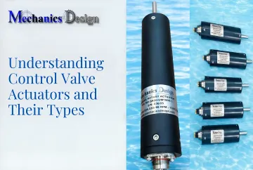
What to Look for When Selecting a Subsea Actuator
Depth and Pressure Rating
The actuator's pressure compensation system must be rated for your maximum operating depth. Compensation to 3,000 meters covers most industrial and deep commercial subsea applications, but always verify against project-specific requirements. NV Mechanics Design Ltd. offers actuators rated to 3,000 meters for standard applications and 6,000-meter variants for extreme deep-sea work.
Actuation Type and Motion Output
Match the actuator type to your valve or mechanism:
- Linear actuators for gate valves requiring straight-line push/pull motion
- Scotch yoke rotary for ball valves needing high breakaway torque
- Rack-and-pinion rotary for throttling valves requiring constant torque
Confirm force or torque output meets both operational demands and failsafe spring requirements. Verify compatibility with relevant standards:
- API 6A / ISO 10423: Wellhead and Christmas tree equipment
- API 17D / ISO 13628-4: Subsea production systems and wellhead equipment
Encoder Precision, Control Interface, and Condition Monitoring
For robotic and automated inspection applications:
- Absolute encoder feedback (not incremental) retains position data between power cycles, which is critical for systems that power down between deployments
- RS232, RS422, or equivalent interfaces ensure clean integration with your topside or onboard control system
- Sensor-based condition monitoring enables predictive maintenance and cuts unplanned downtime
Modern actuators broadcast status messages at configurable frequencies — for example, 10 Hz — via serial communication, delivering real-time data for trend analysis and early fault detection.
Frequently Asked Questions
What is a subsea actuator?
A subsea actuator is a device that converts energy (hydraulic, electric, or hybrid) into mechanical motion to operate valves, joints, or mechanisms in underwater environments. It's engineered specifically to withstand high external water pressure, resist saltwater corrosion, and enable remote operation requirements.
What are the four types of actuators?
The four common actuator types are hydraulic, pneumatic, electric, and mechanical (or hybrid). In subsea settings, pneumatic actuators are impractical due to gas compressibility at depth, so hydraulic, electric, and hybrid designs dominate underwater applications.
What is the difference between hydraulic and electric subsea actuators?
Hydraulic actuators deliver high force output and field-proven SIL 3 failsafe capability, but require extensive topside infrastructure (HPUs, umbilical lines) and carry environmental spill risk. Electric actuators use a single power cable, reduce environmental impact, and enable precise control — though they historically required battery-dependent failsafe systems.
How do subsea actuators handle extreme water pressure?
Subsea actuators use pressure compensation systems: a sealed oil-filled compensator equalizes internal actuator pressure with external seawater pressure. This balancing prevents housing implosion without requiring impractically thick walls, enabling operation at depths exceeding 3,000 meters while maintaining reasonable size and weight.
What is a cheaper alternative to linear actuators?
For quarter-turn valve applications, rack-and-pinion or scotch yoke rotary actuators are often more cost-effective than linear designs. Self-contained actuators also reduce total system cost by eliminating external HPUs, umbilical lines, and subsea hydraulic control modules.
Who makes the best actuators?
The right actuator depends on your application: depth rating, failsafe method, power source, and control compatibility all factor in. NV Mechanics Design Ltd. builds purpose-built pressure-compensated actuators for industrial underwater inspection and cleaning, with integrated absolute positioning and self-contained compensation systems rated to 3,000m.