Introduction
Picture a robotic arm in a subsea inspection operation, pressing against a delicate underwater sensor housing at 2,000 meters depth. Apply too little force and the cleaning pad never makes contact; apply too much and you crack a $50,000 component. Or consider an ROV deploying a torque tool against an underwater valve: too little force and the valve stays shut; too much and you damage a sealed subsea interface that costs thousands to recover.
These scenarios illustrate why force awareness is non-negotiable in linear actuator design. According to industry analysis, uncontrolled force application causes up to 30% of automation failures in robotic assembly operations — resulting in component damage, equipment wear, and significant scrap costs.
Modern electric linear actuators address this by moving beyond simple point-to-point positioning: they sense, measure, and respond to the forces they generate in real time. What follows covers force control fundamentals, sensor technologies, control loop architectures, and selection criteria for force-critical subsea applications.
TL;DR
- Force control enables actuators to apply precise, programmable force output rather than just reach a target position
- Integrated sensors (Hall effect, potentiometers, absolute encoders, load cells) deliver continuous position and force feedback
- Two primary strategies: halting motion at a force threshold, or capping force output during continued trajectory
- Essential for grippers, pressing tools, underwater robotics, and variable-contact applications
- Key selection factors include sensor type, drive friction characteristics, and operating environment
What Is Force Control in a Linear Actuator?
Force control refers to the ability of a linear actuator system to regulate the output thrust or load it applies to an object, either independently or in combination with position control. This differs from position-only control, where the actuator moves from point A to point B regardless of forces encountered along the way.
How Electric Actuators Generate Force
Electric linear actuators convert rotary motor torque into linear thrust through mechanical transmissions—typically lead screws, ball screws, or planetary roller screws. Industrial-grade electric actuators now deliver continuous thrust up to 290 kN (65,000 lbf), with planetary roller screw designs enabling direct hydraulic cylinder replacement in heavy-duty applications.
For perspective, common force ranges include:
- Light-duty ROV manipulators: 1,000–5,000 N (220–1,100 lbf)
- Mid-range automation: 10,000–50,000 N (2,200–11,200 lbf)
- Heavy industrial: 100,000–290,000 N (22,500–65,000 lbf)
Position Control vs. Force Control
| Mode | Command Target | Behavior |
|---|---|---|
| Position control | Specific stroke location | Moves until feedback confirms target position, regardless of load |
| Force control | Specific applied load | Stops when force threshold is met, or holds force after motion ceases |
Advanced systems blend both modes — for example, a controlled insertion phase (position) followed by press-fit seating (force) — giving engineers precise command over the full work cycle.
What Is a Force Actuator?
A force actuator is configured with integrated or external force sensing to actively monitor and regulate delivered thrust. These systems close the control loop around actual applied force using load cells, strain gauges, or precision current monitoring — rather than inferring force indirectly from motor current alone.
Motor Current Monitoring as a Force Proxy
One low-cost approach measures current through motor coils to infer torque, which translates to linear force through the known screw pitch and mechanical advantage. This method works best with high-efficiency drive mechanisms: ball screws and planetary roller screws exceed 90% mechanical efficiency, making current-to-force calculations mathematically viable.
Accuracy degrades sharply with friction, though. Lead screws with 15–35% efficiency suffer from stick-slip behavior and high sliding friction, which masks external forces from the controller. In those cases, direct load cell measurement is required for reliable force regulation.
Types of Feedback Sensors Used for Force and Position Control
Feedback sensors are essential for closed-loop control. Without them, the actuator cannot report its actual position or the force it applies, making real-time regulation impossible. Sensor choice impacts accuracy, durability, cost, and system complexity.
Encoder and Hall Effect Sensors
Hall effect sensors detect magnetic field changes as the motor shaft rotates, generating digital pulse counts that track position. Key advantages:
- Compact, robust against most liquids
- Cost-effective for multi-actuator systems requiring synchronization
- Suitable for high-cycle, vibration-prone environments
Main limitation: Hall sensors provide incremental feedback only. If power is lost, position data is lost and a homing routine is required upon restart.
Absolute encoders output a unique positional value for every point in their range and retain that value even after a power cycle. This is critical in subsea or vertical-axis applications where unexpected shutdowns occur and re-homing is impractical or dangerous.
NV Mechanics' pressure-compensated actuators rated to 3,000m water depth use 30-bit absolute encoders that retain position between power cycles, removing the need for post-power-loss homing routines in deep-sea operations.
Potentiometers and Load Cells
Potentiometers (POT sensors) use a wiper sliding on a resistive track to output voltage proportional to stroke position. Unlike Hall sensors, position is retained when power is lost. However, mechanical wear limits lifespan: industrial cermet potentiometers are rated for 1–2 million cycles, with degradation accelerated in high-vibration environments.
Load cells (strain gauge sensors) directly measure applied force by detecting micro-deformation of a metal element under load. Typical specifications:
| Sensor Model | Linearity Error | Repeatability | Application |
|---|---|---|---|
| HBK U10M | 0.02–0.05% | 0.02% | Precision test benches |
| Honeywell Model 31 | ±0.15–0.2% FS | ±0.05–0.1% FS | Industrial automation |
| FUTEK LCM200/300 | ±0.25–0.5% RO | ±0.1% RO | Inline actuator feedback |
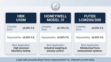
Load cells provide true force measurement rather than inferred data, making them the most reliable method for high-precision force control—far exceeding the accuracy possible via motor current inference.
Reed and Optical Sensors
Where load cells and encoders handle continuous measurement, reed and optical sensors serve a different role: end-of-travel detection and limit protection.
- Reed sensors (magnetic switch-based) detect end-of-stroke positions for safety and limit functions — simple, robust, and providing binary on/off signals rather than continuous data
- Optical sensors use light-blocking wheels to generate counter signals per motor revolution, enabling incremental feedback for homing and limit detection
How Force Control Loops Work in Practice
Modern servo-driven actuators use a cascaded PID control architecture. The innermost loop regulates motor current (torque) with the highest bandwidth via field-oriented control (FOC). The middle loop controls velocity. The outermost loop controls position or force, comparing the measured value against a setpoint and sending corrective signals to the inner loops.
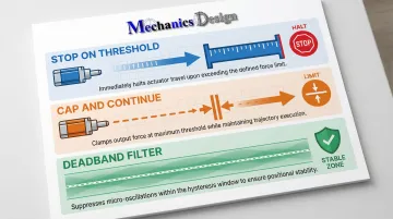
This architecture supports three practical control strategies engineers apply depending on the application:
- Stop on threshold — halt motion the moment measured force hits the target
- Cap and continue — maintain trajectory while clamping force output at a set maximum
- Deadband filtering — suppress small errors near the setpoint to eliminate actuator hunting
Strategy 1: Stop Trajectory When Force Threshold Is Reached
The actuator executes a movement profile while the controller continuously monitors torque command or load cell output. When measured force reaches the programmed threshold—indicating contact with an object—motion halts .
In practice, this suits gripping applications where the object's exact location varies. The actuator advances until it contacts the part, then stops, preventing over-travel and damage.
Strategy 2: Continue Trajectory But Cap Force Output
The controller applies a maximum current (torque) limit to the control loop. The actuator continues its commanded trajectory, but once the force cap is reached, physical position stops advancing even as the commanded position increases. This creates a growing servo error while maintaining constant contact force.
Common application: pressing tools working with materials of inconsistent hardness, or sustained force application during curing, bonding, or assembly operations.
Deadband Filter for Stable Operation
To prevent actuator "hunting" (oscillating around the setpoint near zero error), a deadband filter creates a small hysteresis window around the target force value. All control differences within this zone are suppressed (output = 0), ensuring smooth, stable operation in real-world conditions with sensor noise and structural vibration.
Why Force Feedback Matters in Demanding Robotics Applications
Force feedback becomes essential when contact surfaces are variable, invisible, or deformable—conditions where position control alone cannot ensure safe, effective operation.
Preventing Damage in Robotic Assembly
In automated assembly, uncontrolled force during interference-fit or snap-fit operations leads to component damage, equipment wear, and scrap. Force-torque sensors allow robots to adapt dynamically to part dimension variations, mimicking human finesse to adjust insertion paths in real time. This reduces defects, noise, vibration, and harshness (NVH) issues while increasing throughput.
Teleoperation and Subsea Manipulation
In remotely operated vehicles (ROVs), force feedback relays what the remote mechanism physically "feels" back to the operator, enabling nuanced interaction with subsea structures, pipelines, or marine life without direct line-of-sight. High-end systems like the Ocean One humanoid ROV use 7-DOF arms with force/torque sensors to achieve accurate force rendering. This compensates for ambiguous visual cues in turbid water and prevents damage to delicate underwater equipment.
Subsea ROVs increasingly use all-electric manipulators.pdf) over legacy hydraulics due to more precise positioning and force feedback. NV Mechanics' pressure-compensated actuators—rated to 6,000m depth with absolute encoders on the output shaft—retain position data between power cycles, eliminating the need to re-home after any interruption in the field.
Key Factors When Selecting a Linear Actuator with Force Control
Friction: The Primary Performance Variable
Internal friction in rotary-to-linear actuators masks the force the motor actually applies to an external object, reducing the accuracy of current-based force inference.
| Screw Type | Efficiency | Friction Type | Back-Drivability | Force Inference Viability |
|---|---|---|---|---|
| Ball Screw | >90% | Rolling (low) | High | Excellent with current monitoring |
| Planetary Roller Screw | >90% | Rolling (low) | High | Excellent; current monitoring sufficient |
| Lead/Acme Screw | 15–85% | Sliding (high) | Low (often self-locking) | Poor; requires load cell |
High-friction lead screw drives require external load cells for reliable force control. Lower-friction ball screw or direct-drive systems can rely on motor current monitoring alone.
Sensor Selection for Your Environment
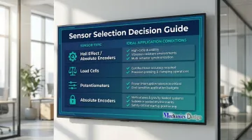
Choose Hall effect or absolute encoders for:
- Continuous, high-cycle operation
- Multi-actuator synchronization
- Environments with vibration or shock
Choose load cells for:
- Applications requiring certified force accuracy (±0.1% or better)
- Precision pressing, assembly, or testing
- Direct force measurement independent of friction
Choose potentiometers for:
- Frequent power interruptions where position memory is needed
- Cost-sensitive applications
- Lower-cycle-count operations
Consider absolute encoders over incremental/Hall for:
- Vertical axes where gravity-driven back-drive could occur during power loss
- Subsea operations where homing routines are dangerous
- Safety-critical applications requiring position knowledge at startup
Sensor choice, however, is only part of the picture — the environment those sensors operate in determines whether any of them will survive long-term.
Environmental Protection and IP Ratings
Standard IP ratings (IP67, IP68, IP69K) define protection against water ingress, but do not account for extreme hydrostatic pressure at ocean depths. True subsea actuators require specialized designs like pressure-balanced oil-filled (PBOF) enclosures.
NV Mechanics' actuators use rolling diaphragm compensators maintaining 0.7–1 bar positive internal pressure, preventing seawater ingress while protecting sensors and electronics at depths up to 6,000 meters.
With environmental constraints established, the following specification questions tie all of these factors together into a single decision framework.
Key Specification Questions
- Required force accuracy: ±0.5%? ±5%? The tolerance defines whether a load cell or current monitoring is the right tool.
- Control mode: Position only, force only, or simultaneous hybrid? Each mode has different sensor and controller requirements.
- Power interruption recovery: Can the system re-home safely, or must position be retained? If not, an absolute encoder is required.
- Operating environment: Temperature range, depth/pressure, contamination exposure — drives IP rating and material selection.
- Drive mechanism friction: High efficiency (ball screw) or high friction (lead screw)? This directly affects force inference accuracy.
Frequently Asked Questions
How to control the position of a linear actuator?
Position is controlled by a closed-loop servo system where a feedback sensor (encoder, Hall effect, or potentiometer) continuously reports the actuator's stroke position to a controller. The controller compares this to the commanded position and adjusts motor output to eliminate the error.
What is a force actuator?
A force actuator is a linear actuator configured with a force-sensing element (integrated load cell or current-monitoring electronics) that allows it to regulate the force it applies to an object, rather than only controlling its position.
What is the purpose of a force sensor?
A force sensor measures the actual load being applied by the actuator in real time and sends that data to the control system. This allows the controller to maintain, limit, or react to force levels, preventing component damage and ensuring consistent process outcomes.
What is the difference between position control and force control in a linear actuator?
Position control commands the actuator to reach a specific location, whatever load it encounters along the way. Force control commands it to apply a specific load, stopping wherever that force threshold is reached. Advanced systems support both modes and can switch between them dynamically.
How does a load cell work in a linear actuator?
A load cell uses a strain gauge bonded to a metal element inside or at the tip of the actuator. As force is applied, the metal micro-deforms, changing the gauge's electrical resistance. A signal processor converts that resistance change into a calibrated force reading sent to the controller.
What types of feedback sensors are used in electric linear actuators?
The four main types are Hall effect sensors, potentiometers, absolute encoders, and load cells/strain gauges. Each suits a different priority: position accuracy, force measurement, power-loss memory retention, or durability in harsh environments like subsea deployments.