Introduction
In hydraulic systems powering industrial machinery, municipal water infrastructure, and underwater robotics, maintaining consistent flow under variable load conditions is where systems succeed or fail. According to ASME, valve losses account for 43% of energy losses in mobile hydraulic applications — a figure that reflects real costs in wasted fuel, accelerated component wear, and unplanned downtime. Pressure compensator valves exist specifically to prevent these losses, yet their function is often misunderstood until something goes wrong.
This article covers how pressure compensator valves work, what failure looks like in practice, and how to evaluate them for your specific application — whether that's a surface hydraulic circuit or a subsea system operating under thousands of meters of hydrostatic pressure.
TLDR
- Pressure compensator valves hold a constant pressure drop across flow control points, keeping flow stable as loads change
- Key functions: flow stability, pressure limiting, reduced component wear, and multi-actuator coordination
- Without pressure compensation, systems experience erratic actuator speeds, pressure spikes, accelerated component failure, and wasted energy
- Especially critical in deep-water subsea systems, where manual intervention isn't an option
- Pre- vs. post-compensation selection depends on actuator count and whether simultaneous load-sharing is required
What Is a Pressure Compensator Valve?
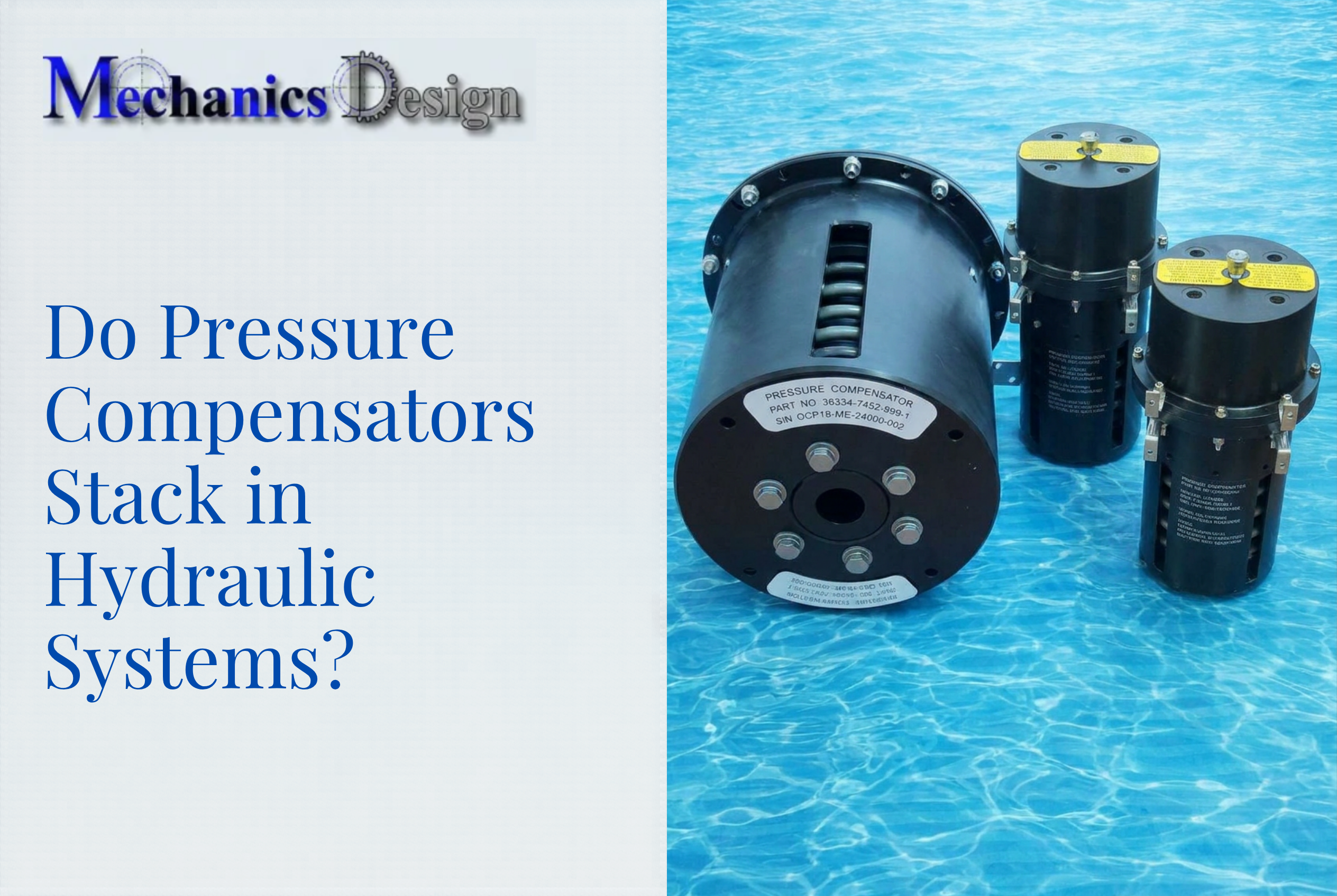
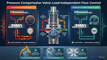
A pressure compensator valve is an automatic hydraulic control device that senses changes in load pressure and adjusts its valve opening to maintain a constant pressure drop across a metering element. This keeps output flow stable regardless of upstream or downstream pressure fluctuations. According to ASME's technical definition, the valve combines a control orifice with a compensator (hydrostat) that modulates its opening to maintain constant pressure drop.
These valves appear in-line with flow control valves, integrated into variable-displacement pumps, or as standalone cartridge valves in multi-actuator hydraulic circuits. Industries relying on this technology include construction machinery (22.2% of the hydraulic market), agriculture (21.2%), and mining operations, where precise actuator control is essential.
The valve doesn't limit flow; instead, it decouples flow rate from load pressure. This makes actuator speed a function of valve setting rather than system load conditions — so a hydraulic arm moves at the same speed whether it's lifting 200 kg or 2,000 kg. In subsea and other high-variability environments, that predictability is the difference between reliable operation and constant manual recalibration.
Key Advantages of Pressure Compensator Valves
The advantages below reflect operational outcomes engineers and system operators track: actuator reliability, maintenance intervals, energy consumption, and system uptime.
Consistent Flow and Precise Actuator Control
A pressure compensator valve ensures flow rate is governed only by the metering element's set opening—not fluctuating load pressures—so actuators move at consistent, predictable speeds. As load-induced pressure on a downstream actuator increases, the compensator spool adjusts to maintain the preset pressure differential (commonly 90 psi), preventing flow from dropping and actuator speed from slowing.
As Fluid Power Journal explains, in uncompensated valves, flow rate fluctuates depending on cylinder load. Heavy loads increase outlet pressure, altering the pressure drop across the valve and changing delivered flow rate. Pressure compensators eliminate this variation—Parker's compensated flow control valves maintain flow settings within ±5% variation over pressure ranges from 100 to 3,000 PSI.
Inconsistent actuator speed leads to positioning errors, jerky motion, and difficulty coordinating multi-function operations. These problems increase rework, safety risks, and operator correction time. In automated production lines or robotic cleaning systems, small speed deviations compound into larger operational problems that disrupt throughput and quality.
This matters most in applications where load conditions shift rapidly: excavator composite actions, multi-axis robotic systems, or tank cleaning equipment where resistance varies with debris and surface conditions. Key metrics affected include actuator positioning accuracy, cycle time consistency, operator intervention frequency, and rework rates.
System Protection and Extended Equipment Life
Pressure compensator valves limit pressure spikes by regulating valve opening during sudden load changes. Without this regulation, hydraulic pumps, pipelines, seals, and actuators absorb damaging pressure surges directly. According to Parker's troubleshooting documentation, pressure peaks can reach 2 to 5 times the adjusted maximum pressure valve and cause brutal failures of components including port plates, rotors, cam rings, and shafts.
An uncompensated system allows load-induced pressure spikes to propagate through the entire circuit, stressing every component. A compensator absorbs these changes locally at the valve level, protecting downstream equipment.
Pressure spikes are a leading cause of seal failure, hose rupture, and pump wear. Industry research shows that mechanical seals account for roughly 80% of pump failures and about two-thirds of centrifugal pump maintenance costs, with emergency seal repairs costing up to 10x more than planned maintenance.
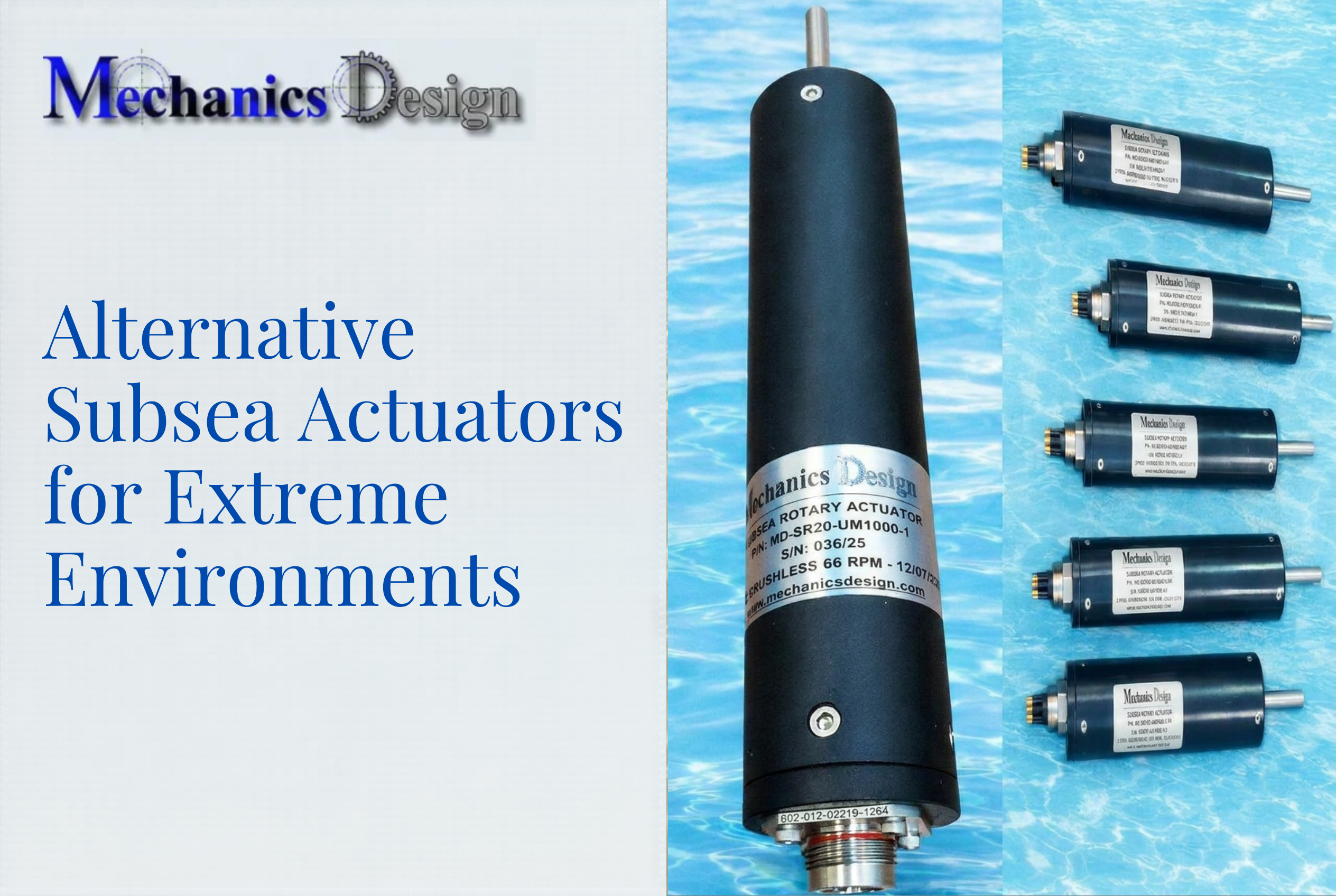
In environments where maintenance access is limited—such as submerged underwater robotics systems operating at depth—uncontrolled pressure differentials can end an operation entirely. NV Mechanics Design's pressure-compensated actuators are oil-filled and rated to 3,000m water depth precisely because a single pressure spike at that depth destroys uncompensated components with no recovery option.
KPIs impacted:
- Mean time between failures (MTBF)
- Maintenance cost per operating hour
- Seal and component replacement frequency
- Unplanned downtime
This protection is most valuable in high-cycle operations, high-depth or high-pressure environments, and applications with sudden or variable load changes where repair access is expensive or impossible.
Energy Efficiency and Multi-Actuator Coordination
Pressure compensator valves reduce energy waste by ensuring the hydraulic pump only supplies the flow and pressure actually demanded by the load. This eliminates constant energy loss from overcoming a fixed high-pressure setting that bleeds power through overflow and heat.
When multiple actuators operate simultaneously and available pump flow falls short of combined demand, load-sharing compensators distribute flow proportionally across all active functions—rather than starving the highest-load actuator.
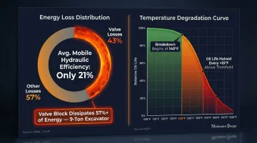
According to Oak Ridge National Laboratory research, the average efficiency in mobile hydraulic applications is just 21%, with valve losses accounting for 43% of total energy losses. In a standard load sensing configuration for a 9-ton excavator, MDPI research shows the valve block dissipates more than 57% of system energy.
Heat is the compounding problem. Throttling excess flow without compensation generates heat that degrades hydraulic fluid faster. Hydraulic fluid research demonstrates that hydraulic oil starts breaking down at around 140°F, with oil life cut in half for every 15° above that temperature. Pressure compensation keeps temperatures lower, which extends fluid service intervals, shrinks cooler requirements, and reduces energy consumption per cycle.
KPIs impacted:
- System energy consumption (kWh per cycle)
- Hydraulic fluid service interval
- Heat exchanger sizing and cost
- Simultaneous actuator coordination accuracy
This advantage compounds most in systems with variable or intermittent load demands, multi-function machines requiring simultaneous operation, and applications with long daily run times where energy costs accumulate.
What Happens When Pressure Compensation Is Missing or Ignored
In an uncompensated system, as load pressure rises, flow through the metering element drops—causing actuators to slow, stall, or behave erratically. This forces operators into constant manual correction and creates unpredictable machine behavior that degrades productivity and safety.
Without pressure limiting, repeated pressure spikes accelerate wear on seals, pump internals, and valve seats. What begins as minor inconsistencies becomes a pattern of more frequent breakdowns, higher maintenance costs, and shorter component service life.
The deeper cost is in how teams respond. Research consistently shows preventive maintenance delivers 5–8x cost savings compared to reactive approaches—a gap that widens as systems age and unplanned failures become more disruptive to operations and scheduling.
Without compensation, maintenance teams spend their time responding to symptoms rather than preventing failures. Common reactive tasks include:
- Replacing worn seals ahead of their expected service life
- Repeatedly adjusting flow and pressure settings to compensate for drift
- Investigating actuator slowdowns with no clear root cause
- Sourcing emergency replacement components under time pressure
This cycle drains maintenance budgets and creates the kind of operational unpredictability that makes scheduling and project delivery unreliable.
How to Get the Most Value from Pressure-Compensated Systems
Pressure compensation works best when the compensator type matches the circuit. According to HydraForce's technical guidance, pre-compensation suits single bi-directional or proportional directional valve applications, while post-compensation with load sharing is essential when multiple actuators must operate simultaneously under varying loads.
Compensation settings—particularly the differential pressure spring value—should be reviewed against actual operating load conditions at commissioning and periodically rechecked. Manufacturers specify minimum pressure differentials for stable flow control:
- Parker FG3PKC series: Minimum 100 PSI (7 bar)
- Danfoss F(C)G-3 series: Minimum 75-125 PSI (5-8.5 bar) depending on model
- Sun Hydraulics: Minimum 200 PSI (14 bar) recommended
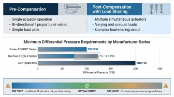
A compensator set too tight wastes energy through unnecessary restriction, while one set too loosely fails to protect against pressure spikes. In extreme or inaccessible deployments, that tradeoff becomes a maintenance liability. Self-compensating designs with all circuitry enclosed inside the housing—as used in NV Mechanics Design Ltd.'s subsea actuators—eliminate field adjustment requirements from the outset.
Conclusion
The pressure compensator valve is an active control element whose function directly determines actuator consistency, equipment longevity, energy efficiency, and the ability to operate reliably in demanding environments. A well-specified and properly maintained compensation system reduces maintenance frequency, extends component life, and enables reliable multi-function operation. These outcomes show up clearly on any hydraulic system's operational record.
Whether the application is a heavy construction machine, an industrial production line, or a subsea ROV running pressure-compensated actuators at depth, pressure compensation is a foundational design requirement. In environments where downtime costs manufacturers an average of $260,000 per hour and hydraulic failures carry six-figure repair bills, specifying pressure compensation is sound engineering and essential risk management.
Frequently Asked Questions
What does a pressure compensator valve do?
It automatically adjusts its valve opening to maintain a constant pressure differential across a metering element, ensuring stable flow output to actuators regardless of changes in load pressure upstream or downstream. This decouples actuator speed from load conditions.
What is a symptom of a worn non-compensated flow control valve?
The most common symptoms include: actuator speed that varies with load, erratic or jerky motion, and difficulty holding consistent positioning. These indicate that flow is no longer being regulated independently of pressure.
How to tell if a hydraulic pressure relief valve is bad?
Key signs include system pressure that will not build to the set point, pressure that exceeds the set point without relief, internal bypassing causing excessive heat, or a system that unloads prematurely. Relief valves and pressure compensators serve different functions—protection versus flow regulation.
What is the difference between a pressure compensator valve and a pressure relief valve?
A pressure relief valve is a safety device that opens to divert flow when system pressure hits a maximum limit. A pressure compensator valve actively regulates flow by maintaining a constant pressure differential across a metering element. The first protects against overpressure; the second controls flow quality across the full operating range.
What should my pressure relief valve be set at?
The relief valve should be set at least 10-15% (approximately 150-200 PSI) above the maximum operating pressure of the highest-load actuator. Keep it below the pressure rating of the weakest component. Always refer to the system designer's specifications and validate under actual load conditions.
Where are pressure compensator valves used in hydraulic systems?
Key application areas include in-line with flow control valves for actuator speed control, integrated into variable-displacement pumps for demand-responsive output, in multi-actuator circuits for load sharing, and in specialized environments including underwater hydraulic systems where consistent performance under variable ambient pressure is essential.