Introduction
Holding force determines whether a linear actuator can maintain its position under sustained axial load without back-driving or displacing. In underwater robotics, unplanned position loss during power interruptions at depth — even minor rod displacement — can compromise mission integrity or create direct hazards.
Dynamic thrust force governs what an actuator can move. Holding force governs what it can resist at standstill. These are fundamentally different specifications, and treating them as interchangeable is a common source of system failures.
This article covers the mechanical principles behind passive self-locking, how screw geometry and orientation affect static load capacity, and the critical distinction between power-dependent and fail-safe holding strategies — with a focus on mission-critical subsea applications.
TL;DR
- Holding force is the maximum axial load a stationary actuator resists without back-driving; datasheets list it separately from dynamic thrust as a "static load rating"
- Lead screws self-lock passively without power; ball screws need continuous motor torque or an external brake to hold position
- Lead angle, thread friction, mounting orientation, and motor energization state all affect real-world holding capacity
- Exceeding the holding force limit causes back-driving — uncontrolled rod movement that leads to position loss and potential load drop in vertical applications
- In subsea applications where power continuity isn't guaranteed, passive self-locking via correct screw selection is the only reliable hold
What Holding Force Represents in a Linear Actuator
Holding force is the maximum sustained axial load a stationary electromechanical linear actuator can resist without the rod displacing, expressed in Newtons or pounds-force. This is a design parameter — determined primarily by screw thread geometry, nut material friction characteristics, and supplementary braking — not a derived consequence of the dynamic thrust rating. According to ISO 3408-5, the basic static axial load rating ($C_{0a}$) represents the maximum purely axial static load that creates permanent deformation equal to 0.0001 times the rolling element diameter. According to ISO 3408-5, the basic static axial load rating ($C_{0a}$) represents the maximum purely axial static load that creates permanent deformation equal to 0.0001 times the rolling element diameter. This establishes a formal definition distinct from dynamic load capacity.
Electromechanical linear actuators employ three distinct holding modes:
- Passive mechanical self-locking: The lead angle of the screw thread is smaller than the friction angle, preventing back-driving without any power input.
- Energized motor holding: Continuous current produces motor torque to maintain position while power is applied.
- Supplementary external braking: A mechanical or electromagnetic brake arrests motion independently of the screw or motor.

Only passive self-locking provides fail-safe holding during a power interruption.
In underwater actuator applications rated to 3,000–6,000 meters depth, such as those used in subsea inspection and cleaning operations, passive self-locking is the foundational holding strategy. Pressure-compensated actuators designed for these environments depend on geometry-defined self-locking to maintain mechanical position during any unplanned de-energization event.
While integrated absolute encoders that retain position data between power cycles provide verification that holding was maintained, the mechanical holding capacity must be inherent to the screw design.
Factors That Influence Holding Force in Real-World Operation
Screw Lead and Thread Geometry
Screw lead is the primary mechanical variable governing passive holding. A screw is self-locking when the lead angle ($\lambda$) is less than the friction angle, defined as the arctangent of the coefficient of friction ($\mu$) between thread and nut. Mathematically, self-locking requires $\lambda < \arctan(\mu)$.
ACME and modified lead screws meet this condition by design because their coarser pitch creates smaller lead angles. Ball screws operate at >90% mechanical efficiency with lead angles that exceed typical friction angles, eliminating any passive holding capability. Geometry fixes the self-locking threshold at the design stage through screw selection. Field adjustment is not possible.
Mounting Orientation
Vertical mounting imposes the full gravitational component of the suspended load directly on the holding mechanism. Horizontal mounting reduces this to friction and externally applied axial forces. Vertical applications consistently require the most conservative holding force margins because any degradation in friction or thread wear directly translates to back-driving risk.
This worst-case scenario becomes especially consequential in subsea deployments. For actuators operating on vertical tank walls or in subsea inspection applications, the holding mechanism must simultaneously resist:
- 100% of the payload weight under static load
- Dynamic disturbances from water currents
- Operational vibration transmitted through the structure
Motor Energization State
When the motor remains powered in a stationary position, its holding torque supplements mechanical locking. Stepper motors possess built-in holding torque when energized at standstill, but this torque degrades by approximately 0.4% per °C of temperature rise. Brushless DC (BLDC) and servo motors provide essentially zero holding torque when de-energized.
Relying solely on energized motor torque for static position retention is a critical safety risk. When power is removed, only passive thread geometry or a brake can prevent displacement. This distinction separates fail-safe designs from power-dependent ones, and it carries particular weight in subsea operations where power interruption at depth is a safety-critical failure mode.
Mechanical Efficiency Degradation
Over service life, several compounding factors erode the passive self-locking margin before any visible mechanical damage appears:
- Thread wear and contamination reduce the effective friction coefficient at the screw-nut interface
- Lubrication breakdown shifts the friction angle closer to — or below — the lead angle
- Polymer nut creep causes time-dependent stress relaxation that alters thread geometry and reduces preload
These degradation mechanisms must inform both maintenance intervals and safety factor selection. An actuator that self-locks reliably when new can begin to slip after thousands of hours under sustained load as the friction angle gradually falls below the lead angle.
The Range of Holding Force Values
Holding force is bounded on the upper end by structural load limits of the screw thread, nut material, and housing assembly. On the lower end, it is constrained by the minimum friction margin required to prevent back-driving under sustained load, vibration, and thermal cycling.
Nominal Operating Range
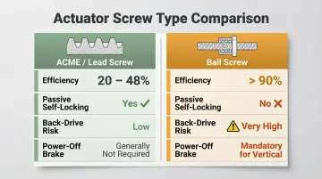
The ratio of static holding force to dynamic thrust force varies significantly by screw type. ACME and lead screw actuators can often self-lock at loads equal to or exceeding their dynamic thrust rating due to their mechanical inefficiency. Ball screw actuators have near-zero holding capacity at any load because their high efficiency eliminates the friction needed for self-locking.
| Actuator Type | Typical Efficiency | Passive Self-Locking | Back-Drive Risk | Power-Off Brake Required | |---------------|-------------------|---------------------|-----------------|--------------------------|\n| ACME / Lead Screw | 20–48% | Yes (if $\lambda < \arctan(\mu)$) | Low | Generally No | | Ball Screw | >90% | No | Very High | Yes (Mandatory for vertical) |
Nominal holding force ratings apply under standard operating temperature range, clean and properly lubricated thread interface, axial loading only (no side loads), and the designated orientation. Any deviation from these conditions narrows the effective holding range.
Allowable Tolerance and Boundary Limits
The upper structural boundary occurs where thread flanks begin to deform plastically, nut material yields, or housing mounting points begin to fatigue. This is governed by material yield strength and appears on datasheets as the maximum static load limit. The lower practical limit represents the minimum thread friction margin required to resist back-driving under low-level vibration and thermal cycling.
As the actuator accumulates cycles, the friction coefficient decreases and that lower margin shrinks. Nominal holding force can become unreliable before any visible mechanical damage appears. This makes periodic load testing essential — visual inspection alone will not catch the degradation.
Safe Operating Margin
Engineering safety factors of 1.5x to 2.0x the maximum expected static load are standard practice in linear actuator selection. This margin compensates for:
- Shock loads and transient load spikes
- Unexpected orientation changes during operation
- Thermal variation affecting friction coefficients
- Service-life degradation of thread surfaces
- Installation misalignment introducing side loads
Designing exactly to the boundary leaves no buffer. Under vibration, back-driving can occur intermittently. Thread wear accelerates each time slip happens, and when the degraded friction margin is finally exhausted, position loss is sudden rather than gradual.
Key Technical Properties of Holding Force
Passive Self-Locking: Lead Angle and Friction Angle Relationship
Self-locking is achieved when the helix angle of the lead screw is less than the arctangent of the coefficient of friction between thread and nut material. This is a fixed, geometry-defined characteristic that cannot be adjusted in the field.
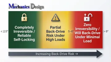
Typical lead angle thresholds for common screw designs:
- Lead angles < 2.5°: Completely irreversible, reliable self-locking
- Lead angles 5–6°: May exhibit some back-drive under high loads
- Lead angles > 6°: Zero irreversibility, will back-drive under minimal axial load
In underwater and subsea robotic applications, where power interruption at operating depth is a safety-critical failure mode, passive self-locking through correct screw selection is essential. Actuator systems designed for deep-water inspection and cleaning operations depend on this property to hold mechanical position during any unplanned de-energization event — no power, no control signal, and no active braking required.
Stability and Variability Under Sustained Load
Even a geometrically self-locking actuator exhibits holding force variability over time. Three mechanisms drive this variability:
- Material creep: Polymer nut materials deform progressively under sustained compression
- Lubrication redistribution: Sustained axial load shifts the effective friction coefficient at thread contact points
- Thermal expansion: Housing growth under temperature change alters preload and screw-nut contact geometry
These effects cause slow position drift in long-dwell applications — subsea inspection platforms, for instance, may hold position for hours while conducting surveys. Mitigation strategies include:
- Selecting creep-resistant nut materials (bronze or hardened steel instead of acetal polymers)
- Implementing periodic re-zeroing procedures using absolute position feedback
- Monitoring position data retained between power cycles to detect any drift
An actuator held near its holding force limit for an extended period may also exhibit elastic recovery (spring-back) when the load is released. Precision robotic systems account for this using absolute encoders that retain position data between power cycles, enabling detection and correction of any displacement that occurred during the hold.
Lead Selection and Dynamic Speed Trade-offs
Finer pitch (lower lead) produces a smaller helix angle and stronger passive self-locking, but reduces linear speed and increases heat generation under dynamic loads. Coarser pitch improves speed and thermal performance but reduces or eliminates passive holding capability.
This trade-off is managed through design compromises:
- Applications requiring reliable power-off holding at moderate speed: Multi-start ACME screws provide increased speed (lead = pitch × number of starts) while maintaining acceptable lead angles
- High-speed applications: Ball screws combined with integrated electromagnetic brakes sacrifice passive holding for maximum efficiency and speed
The engineering decision depends on application priorities. Underwater actuators in mission-critical roles typically prioritize passive holding over speed, accepting lower linear velocities to ensure reliable position hold after power loss.
How Holding Force Is Specified, Measured, and Validated
Specification and Documentation
Holding force appears on datasheets under terms like "static load rating," "maximum static axial load," or "holding force." This value is listed separately from dynamic thrust, and the orientation (vertical vs. horizontal) and power state (energized vs. de-energized) under which the rating was determined must be confirmed before applying it to a specific design.
The distinction between rated and tested holding force matters. Manufacturer-rated values are derived from theoretical thread geometry and friction coefficients. Tested values account for real assembly variation and actual contact conditions. When both are listed, always use the tested value for safety-critical designs.
Measurement and Verification Methods
The standard method for verifying holding force uses a calibrated load cell to apply a sustained axial force to the stationary, de-energized actuator while a displacement sensor monitors rod position over a defined dwell period (a set hold time). Any displacement indicates the self-locking threshold has been reached or exceeded.
Test procedure varies by configuration:
- Passive self-locking: De-energize the motor completely and disengage any brakes so thread friction alone resists the applied load
- Powered-hold: Keep the motor energized at rated holding current throughout the test
- Real-world commissioning: Account for installation misalignment, contamination, thermal cycling, and wear — factors that controlled lab tests cannot replicate
Actuators with absolute position encoders that retain data between power cycles offer continuous field validation: compare the stored pre-interruption position against the post-recovery reading after any de-energization event. Consistent agreement between the two confirms the holding mechanism performed as expected.
Implications of Exceeded Holding Force and Common Misinterpretations
Back-Driving Failure Mechanism
When holding force is exceeded, the lead screw rotates under axial load without commanded motor input — causing uncontrolled rod displacement. In vertical applications, that means uncontrolled load descent.
The resulting hazard profile in automation and robotic systems includes equipment damage, payload drop, and personnel safety risks wherever a held position defines a safety boundary.
Accelerated Wear Mode
Repeated near-limit loading causes progressive surface damage to the nut and screw through elevated thread flank contact stress. This reduces dynamic efficiency over time while the actuator may still appear to hold statically — until abrupt failure occurs. Screen for this failure mode through periodic load testing; visual inspection alone won't catch it.
Common Misinterpretations
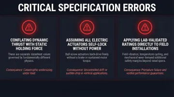
Three critical specification errors occur frequently in practice:
Conflating dynamic thrust with static holding force. These are separate datasheet values governed by different physics. Dynamic load capacity determines fatigue life during motion; static capacity determines what the actuator can hold at rest. Using the dynamic rating to evaluate holding capability is a common — and potentially dangerous — specification error.
Assuming all electric linear actuators self-lock without power. Self-locking only applies to lead screw designs with lead angles below the friction angle threshold. Ball screw actuators back-drive under load without continuous motor torque or an external brake. Specify a ball screw on a vertical axis without a brake and the payload drops the moment power is cut.
Applying lab-validated holding force directly to field installations. Lab data doesn't account for field vibration, temperature swings, lubrication changes, or service-life degradation. Without appropriate safety factors built in, slipping occurs in real installations even when the nominal holding force looks adequate on paper.
Conclusion
Holding force is a governing mechanical parameter, shaped by both fixed design choices and time-dependent operating conditions. Reliable linear actuator design depends on getting several things right:
- Treating static and dynamic ratings as distinct values, not interchangeable figures
- Applying safety margins calibrated to the specific deployment environment
- Accounting for wear, lubrication state, orientation, and temperature as active variables
- Selecting passive self-locking thread geometries wherever power-off holding is a safety requirement
In subsea applications, power interruption at depth is a safety-critical event. Passive self-locking through correct screw selection is the only reliable holding strategy in these conditions — not brake systems or active power retention.
Absolute encoders that retain position data between power cycles support verification of holding performance, but the mechanical holding capacity itself must be inherent to the thread geometry. For mission-critical deployments, validating holding performance through physical testing is essential. Rated values are starting points, not guarantees under real field conditions.
Frequently Asked Questions
How much weight can linear actuators hold?
Holding capacity depends on screw type, actuator size, and orientation. Self-locking ACME screw actuators resist their rated static axial load without power; ball screw designs require a brake or continuous motor torque. Always apply a safety margin of 1.5–2× the maximum expected load to datasheet static ratings.
How to calculate actuator force?
For vertical mounts, required force equals the load weight. For angled mounts, use F = Load / sin(θ), where θ is the angle between the actuator axis and the load direction. Add a 25–50% safety margin above the calculated peak to account for friction, dynamic effects, and wear over service life.
Are linear actuators stronger pushing or pulling?
Electric linear actuators typically produce equal push and pull force because the lead screw and motor operate symmetrically in both directions. Hydraulic and pneumatic cylinders, by contrast, generate lower retraction (pull) force because the rod reduces the effective piston area on the retraction side.
What is the thrust force of an actuator?
Thrust force is the maximum axial force an actuator can generate while in motion under rated speed and voltage. This is distinct from static holding force — thrust force governs what the actuator can move, while holding force governs what it can resist at standstill. The two values are not interchangeable.
Can a linear actuator hold its position when power is turned off?
Self-locking lead screw designs (ACME and modified screws with low lead angle) maintain position without power because the thread geometry prevents back-driving. Ball screws cannot self-lock passively and will back-drive under load unless an external brake or continuous motor torque is applied.
What is the difference between static load and dynamic load in a linear actuator?
Dynamic load (thrust force) is the maximum force generated while the rod is in motion; static load (holding force) is the maximum axial load resisted at standstill. These are separate datasheet values — applying the dynamic rating to evaluate holding capability is a common and potentially dangerous specification error.