Introduction
Actuator closing force — the total force an actuator must generate to fully close a valve or mechanism against process pressure, friction, and seating resistance — is the foundational parameter in any actuation system design. The actual calculation involves multiple force contributions that vary by actuator type, valve design, operating pressure, and application environment — and underspecifying any one of them leads to leaking valves, actuator failure, or premature wear.
A 2021 Chemical Safety Board investigation at a Chevron Phillips facility found that a fuel gas isolation valve failed to close because frozen instrument air prevented the actuator from delivering adequate closing force — resulting in ruptured heater tubes and a $5.8 million fire. In a separate incident documented by PHMSA, a gas transmission valve failed to close during a pipeline rupture because the actuator relied solely on pipeline gas pressure, which dropped too low to provide the required closing thrust.
Both failures trace back to the same root cause: closing force was never rigorously calculated for worst-case conditions.
This article walks through the exact step-by-step calculation method, the key variables involved, how actuator type changes the approach, and the most common errors to avoid.
TL;DR
- Actuator closing force = Static Unbalance Force + Packing Friction + Seat Load — sum all three components before selecting an actuator
- Static unbalance force is higher for unbalanced trim than pressure-balanced trim, often by a wide margin
- Packing friction and seat load values come from the valve manufacturer's specs and vary by stem size and shutoff class
- Apply a safety factor (typically 1.25–1.5×) to the final required closing force before selecting an actuator
- Actuator type (single-acting vs. double-acting) determines how closing force is generated and must match your fail-safe requirements
How to Calculate Actuator Closing Force
Step 1: Determine the Static Unbalance Force
Static unbalance force is the resistance created by process fluid pressure acting on the valve's closure element at shutoff. The magnitude of this force depends entirely on whether the valve uses pressure-balanced or unbalanced trim.
For unbalanced trim: Calculate the unbalanced area using the port diameter:
- Unbalanced Area = π × (Port Diameter / 2)²
- Static Unbalance Force = Unbalanced Area × Upstream Static Pressure (P1)
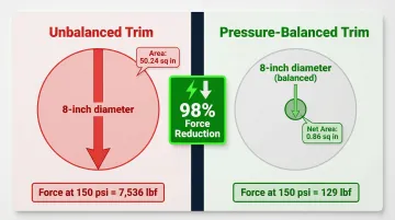
For example, an 8-inch unbalanced single-seated valve has an unbalanced area of 50.24 square inches. At 150 psi differential pressure, the static unbalance force equals 7,536 lbf.
For pressure-balanced trim: Consult the valve manufacturer's datasheet for the published unbalanced area, which is significantly smaller than the full port area. Pressure-balanced trims use sleeve/plug designs with vent holes to equalize pressure on both sides of the plug, reducing the net off-balance area by over 95% in large port sizes. Using the same 8-inch valve with balanced trim, the unbalanced area drops to just 0.86 square inches, reducing the static unbalance force to only 129 lbf at 150 psi — a 98% reduction.
Flow direction matters: In a "flow-to-open" configuration, the process fluid applies force that tends to move the valve toward the open position, opposing the actuator's closing force. Confirm flow direction from the valve's design documentation to determine whether static unbalance force assists or opposes closing.
Step 2: Determine the Packing Friction Force
Packing friction is the resistance created by the stem seal as it moves through the packing box. It acts against the actuator in both directions and must be fully overcome during closing.
How to find packing friction: Look up the packing friction value from the valve manufacturer's documentation based on:
- Stem diameter
- Packing ring type (PTFE V-ring, graphite, engineered polymer)
- Number of packing sets (single vs. double)
Material matters: PTFE packing offers the lowest friction coefficient but is limited by temperature (typically up to 450°F). Graphite packing can withstand extreme temperatures (up to 1200°F in steam) but generates significantly higher friction — often 4× to 6× more than PTFE.
| Stem Size | PTFE Packing (Single) | Graphite Packing (Single, Class 300) |
|---|---|---|
| 3/8 inch | 38 lbf | 190 lbf |
| 1/2 inch | 50 lbf | 230 lbf |
| 3/4 inch | 75 lbf | 440 lbf |
| 1 inch | 100 lbf | 610 lbf |
Wear and overtightening: Packing systems are often overtightened during installation or maintenance to stop leaks. Applying stress beyond the target range serves no sealing benefit but drastically increases friction.
PTFE-based packing consistently produces lower friction than yarn or graphite alternatives — a meaningful advantage in applications where actuator output is tightly sized.
If manufacturer data is unavailable: Friction values increase with stem diameter, higher-temperature packing materials, and double-packing configurations. For rough estimates, expect single PTFE packing to range from 40–100 lbf for stems under 1 inch, and graphite packing to range from 200–600 lbf in the same size range.
Step 3: Determine the Seat Load Force
Seat loading is the minimum contact force the actuator must apply between the plug/disc and the seat to achieve the required shutoff class per ANSI/FCI 70-2.
Seat load calculation: Seat Load (lbf) = Port Circumference × Seat Load Requirement (lbf/in)
Where:
- Port Circumference = π × Port Diameter
- Seat Load Requirement (lbf/in) is specified by the valve OEM based on shutoff class and trim material (soft seat vs. metal seat)
ANSI/FCI 70-2 Leakage Classes:
| Leakage Class | Typical Seat Material | Recommended Seat Load (lbf per lineal inch) |
|---|---|---|
| Class II | Metal | 20 lbf/in |
| Class III | Metal | 40 lbf/in |
| Class IV | Metal | 40–80 lbf/in |
| Class VI | Soft (PTFE/Elastomer) | 300 lbf/in (for metal seat equivalent) |
Material tradeoffs: Softer seat materials like PTFE require less closing force than metal-to-metal seating, but trade off temperature and pressure resistance. Most manufacturers recommend seat loads above the tested minimum to extend seat life in service.
Step 4: Sum All Forces, Apply Safety Factor, and Select Actuator
Required Closing Force = Static Unbalance + Packing Friction + Seat Load
Apply a safety factor: Multiply the required closing force by 1.25 to 1.5× to account for manufacturing tolerances, wear over the valve lifecycle, and unknown operating variables. The final result is the minimum actuator output force specification.
For example:
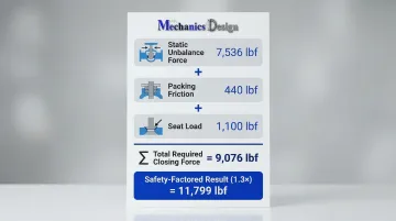
- Static Unbalance Force: 7,536 lbf
- Packing Friction: 440 lbf
- Seat Load: 1,100 lbf
- Total Required Closing Force: 9,076 lbf
- Safety-Factored Closing Force (1.3×): 11,799 lbf
Select an actuator: Compare the safety-factored closing force against the actuator's rated output at the operating supply pressure (hydraulic, pneumatic, or electric). Ensure the actuator output meets or exceeds this value without exceeding the valve's Maximum Allowable Stem Torque (MAST) to prevent stem or seat damage.
Key Variables That Affect Actuator Closing Force
While the calculation formula is consistent, the magnitude of each force component varies depending on the variables below. Misidentifying even one can lead to under- or over-sizing.
Process Differential Pressure (ΔP)
The differential pressure across the valve at shutoff (the difference between upstream P1 and downstream P2) is the primary driver of static unbalance force. Higher differential pressure at close directly increases the force required.
Some systems see pressure spikes at close that exceed normal operating conditions. In water and wastewater systems, rapid valve closure causes water hammer — a sudden change in fluid velocity that converts kinetic energy into a pressure wave. The Joukowsky equation predicts this instantaneous pressure rise, which can exceed 5 to 10 times normal working pressure.
Stopping a 10 ft/s water flow instantaneously, for example, can generate a spike of over 327 psi above operating pressure. Actuators must be sized to seat the valve against these transient conditions, not just steady-state flow.
Valve Trim Type and Port Size
Two trim-related factors drive force requirements:
- Pressure-balanced trim uses process pressure to counteract itself, reducing unbalanced force — but seal rings add friction. The tradeoff: smaller actuators, more complex valve internals.
- Port diameter determines both the unbalanced area and seat load circumference. An 8-inch port has over 50 sq. in. of unbalanced area versus just 1.35 sq. in. for a 1-5/16-inch port — a 37× difference that compounds across all three force components.
Packing Material and Condition
Fresh PTFE packing and well-lubricated graphite have measurably different friction coefficients. Worn or overtightened packing can multiply friction forces well beyond original spec.
Industry data shows packing consolidation and thermal cycling increase friction by 20–50% over the valve's service life. Safety factors exist precisely for this reason — the valve must close reliably well after initial installation.
Operating Temperature
High temperatures cause thermal expansion of valve and actuator components, which can increase packing friction and alter the effective seat load. Designers in high-temperature systems must adjust calculations accordingly. Graphite packing, while capable of withstanding extreme temperatures, operates at higher stress levels and produces measurably higher friction.
Supply Pressure (for Fluid Power Actuators)
For hydraulic or pneumatic actuators, the available supply pressure at the actuator determines the maximum deliverable force: Force = Pressure × Effective Piston Area
A pressure drop in the supply line at the moment of closing can reduce available force below the calculated requirement. This is especially critical in emergency shutdown (ESD) applications where the actuator must close reliably even when primary utilities are compromised.
Closing Force for Single-Acting vs. Double-Acting Actuators
Actuator type fundamentally changes how closing force is generated, delivered, and maintained. The calculation must account for this before selecting an actuator.
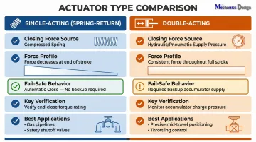
Single-Acting (Spring-Return) Actuators
In a spring-return actuator (typically fail-closed), the closing force is delivered by the spring, not by supply pressure. The spring force must exceed the sum of static unbalance + packing friction + seat load at the point of full closure.
One critical constraint: spring force is at its minimum when fully compressed (end of stroke), which is the worst case for closing. The designer must verify that spring force at full stroke still exceeds the required closing force. This value — called "end close torque" — is distinct from the break-to-close torque required to initially begin movement.
Double-Acting Actuators
In a double-acting actuator, closing is accomplished by applying supply pressure to the opposite side of the piston. The closing force is a function of supply pressure × effective piston area and remains more consistent throughout stroke compared to spring-return.
For fail-safe applications, a backup supply must be sized to maintain closing force on loss of primary supply. IOGP JIP33 S-707 mandates an air receiver or hydraulic accumulator capable of delivering at least three full strokes while holding minimum supply pressure.
Matching Actuator Type to Application
Choosing the right type depends on your fail-safe requirements and control precision:
- Single-acting (spring-return): Preferred for fail-safe automatic-close applications — water treatment, gas pipelines, and safety shutoff valves
- Double-acting: Used where equal force is needed in both directions or where precise mid-travel positioning is required
Subsea and pressure-compensated environments: Subsea deployments introduce a variable that surface calculations ignore entirely: external hydrostatic pressure. At 3,000 m depth it exceeds 4,350 psi; at 6,000 m it reaches 8,700 psi — enough to crush or immobilize a standard actuator.
NV Mechanics Design addresses this with oil-filled, pressure-compensated actuators that equalize pressure across dynamic seals, keeping seal friction manageable at any rated depth. This changes the effective closing force calculation in ways that standard above-ground formulas don't capture.
Common Mistakes in Actuator Closing Force Calculations
Using Maximum Operating Pressure Instead of Shutoff Differential Pressure
The pressure a valve sees at closure is not always the same as normal operating pressure. Identify which condition governs — shutoff or operating — and use the higher value in your calculation.
A 2002 CSB investigation at DPC Enterprises illustrates the consequence of getting this wrong. Emergency shutdown valves failed to close during a chlorine release because internal corrosion had drastically increased valve friction beyond the actuator's rated closing capacity. The actuators were sized for clean, like-new conditions, not the degraded worst case.
Ignoring Packing Friction
Engineers focused on fluid forces often omit packing friction entirely. In smaller valves, it can represent a significant portion of the required closing force. In worn or overtightened packing configurations, it can dominate the calculation outright.
For a 3/4-inch stem with graphite packing, friction alone can exceed 440 lbf — more than the static unbalance force in many low-pressure systems. That's not a rounding error; it's a sizing failure waiting to happen.
Failing to Verify Against MAST
Confirming adequate closing force is only half the check. The actuator's maximum output must also stay below the valve's Maximum Allowable Stem Torque (MAST) — the upper limit a quarter-turn valve stem can handle before yielding or shearing.
An oversized actuator running at full supply pressure can deliver more torque than the stem is rated for, causing stem deformation or seat damage. Bigger is not always safer.
Not Applying a Safety Factor
Sizing an actuator to exactly meet the theoretical minimum leaves no room for wear, pressure variations, temperature effects, or packing aging over time. These factors accumulate — and they rarely favor you.
Always apply a documented safety factor of 1.25× to 1.5× and record the rationale. If the application involves corrosive media or infrequent cycling, lean toward the higher end of that range.
When Actuator Closing Force Calculations Matter Most
While actuator closing force always needs to be verified at design stage, certain applications make calculation accuracy especially critical due to the consequences of failure.
High-stakes shutoff applications: Emergency shutoff valves in chemical or oil and gas systems, isolation valves in potable water reservoirs, and fire-safe valve systems all demand precise closing force calculations. An under-actuated valve that fails to fully close can cause contamination, process loss, or safety incidents.
An EPA alert on Excess Flow Valves documented a fatal 1998 propane explosion in Iowa where downstream piping restrictions prevented flow from reaching the threshold needed to trigger the valve's closing mechanism. The valve failed to close. Two firefighters were killed and seven others injured.
Remote or inaccessible deployments: Where the actuator cannot be manually adjusted or replaced easily once installed, closing force calculations must include a more conservative safety factor (1.5× to 2.0×) and account for long-term packing wear and seal degradation. This is particularly relevant in underwater, buried, or offshore actuator installations.
Subsea deployments add another layer of complexity: hydrostatic pressure at depth directly affects actuation force requirements. NV Mechanics Design's pressure-compensated electric linear and rotary actuators — rated to 3,000–6,000 meters depth — use oil-filled housings and compensators that maintain 0.7 to 1 bar positive internal pressure to prevent seawater ingress.
Built from stainless steel 316 or titanium, these actuators deliver axial forces from 1,000 N (220 lbf) to 77,500 N (7,000 lbf) and torques up to 27 Nm (19 ft-lbf). They support subsea valve control across offshore oil and gas infrastructure, underwater robotics, and water reservoir applications where long-term reliability is critical.

Frequently Asked Questions
How do you calculate actuator closing force?
Actuator closing force is calculated by summing three components: static unbalance force (unbalanced area × differential pressure), packing friction, and seat load. Apply a safety factor of 1.25–1.5× to the total to determine the minimum required actuator output.
What is the shut-off pressure of an actuator?
Shut-off pressure refers to the maximum differential pressure across the valve that the actuator can hold closed. It is determined by the actuator's closing force output relative to the force the process fluid exerts on the closure element; exceeding it results in valve leakage.
What is the torque of an actuator?
Actuator torque is the rotational force the actuator delivers to turn a rotary valve (such as a ball or butterfly valve) and is measured in Newton-meters (Nm) or foot-pounds (ft-lbs). For linear (sliding-stem) valves, the equivalent is thrust, measured in pounds-force (lbf) or Newtons.
What is the difference between break torque and end torque in actuator closing?
Break-to-close torque initiates movement from fully open and is often the highest demand point, driven by static friction and peak pressure differential. End-close torque applies at full closure and must exceed the seat load requirement to seal the valve.
How does actuator type (single-acting vs. double-acting) affect closing force?
Single-acting actuators rely on a compressed spring for closing force, which decreases as it extends — verify worst-case output at end of stroke. Double-acting actuators use supply pressure for more consistent force but require a backup supply source for fail-safe operation.
What safety factor should be applied to actuator closing force calculations?
Standard practice calls for a safety factor of 1.25× to 1.5× on the calculated closing force. More demanding applications — high wear rates, critical service, or hard-to-access installations — warrant the upper end of that range.