Introduction
Control valve actuators translate control signals into physical valve movement, enabling precise flow regulation across industrial systems — from chemical plants and refineries to water treatment facilities and subsea infrastructure. Without them, automated control loops cannot function.
Actuator selection is a critical decision point in any process environment. Specify the wrong type and the consequences cascade: process inefficiency, safety risks, premature equipment failure, and expensive rework. Common mismatches include:
- A pneumatic actuator installed where no compressed air infrastructure exists
- An electric actuator without explosion-proof certification in a hazardous zone
- A hydraulic actuator on a modulating valve where response speed is critical
This article covers what control valve actuators are, the four main types (pneumatic, electric, hydraulic, and manual), how each differs in design and application, and how to select the right actuator for your specific process requirements.
TL;DR
- A control valve actuator moves a valve open or closed based on manual or automated command
- Four main types: pneumatic, electric, hydraulic, and manual—each suited to different environments and control needs
- Pneumatic actuators dominate process industries for their speed and reliability
- Electric actuators deliver precision positioning and remote control where power infrastructure exists
- Selection depends on power source, response speed, torque demands, environmental conditions, and control system compatibility
- Mismatched actuator selection is a leading cause of valve system failures—wrong choices lead to premature wear, process downtime, and unplanned replacements
What Is a Control Valve Actuator?
A control valve actuator is the mechanical or electromechanical device mounted to a valve that provides the motive force to open, close, or precisely position the valve trim in response to a signal or manual input.
Put simply: the valve body controls the fluid; the actuator controls the valve. Within a broader control loop, the actuator is the interface between your control system and the physical process.
A controller sends a signal, the actuator converts it into physical movement, and the valve adjusts flow accordingly. Signal types include:
- Pneumatic — compressed air pressure
- Electrical — current or voltage from a controller
- Hydraulic — pressurized fluid
Each signal type drives either linear or rotary movement, depending on the valve design.
This distinction matters because selecting an actuator means integrating a complete control system architecture, not just fitting a component to a valve body.
Why Control Valve Actuators Matter in Industrial Systems
Without a correctly matched actuator, a control valve cannot respond accurately to process demands. Poor flow regulation, pressure swings, and valve hunting are common results — as are unsafe conditions in critical systems like chemical processing, water treatment, and pipeline management.
Common consequences of actuator mismatch:
- Slow response times during emergency shutdowns
- Valve hunting and instability in modulating control applications
- Premature mechanical wear from excessive cycling or force
- Complete control loop failure requiring system shutdown
These consequences make clear that actuator selection is not interchangeable across applications. The same valve body may require different actuators depending on process fluid properties, environmental conditions, and control requirements. A ball valve in a refinery's flare system needs different actuation than the same valve model in a water distribution network.
Types of Control Valve Actuators
Choosing the right actuator type comes down to five factors: available power source, required force or torque, response speed, control precision, and operating environment. Each actuator technology makes different trade-offs across these variables.
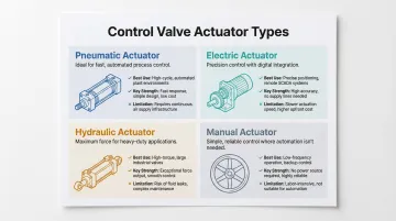
Pneumatic Actuators
How they work: Pneumatic actuators use compressed air (or gas) pressure acting on a diaphragm or piston to generate linear or rotary force on the valve stem. Diaphragm types offer lower friction and better precision for throttling applications. Piston types deliver higher force and longer stroke for demanding shutoff valves.
Best suited for:
- Process plants with existing compressed air infrastructure
- Water and wastewater treatment facilities
- Refineries, chemical plants, and food processing operations
- Hazardous areas where electrical ignition risk must be eliminated
Key strengths:
- Fast response—typically 1-3 seconds for full stroke
- Built-in failsafe capability through spring-return design
- Simple, reliable construction with few moving parts
- No electrical ignition risk in explosive atmospheres
Limitations:
- Require centralized compressed air supply system (infrastructure cost)
- Air compressibility introduces slight imprecision in modulating applications
- Air quality (moisture, contamination) must be maintained to prevent internal corrosion
- Energy inefficiency—compressed air systems consume 60-80% more energy than electric actuators in continuous modulating service
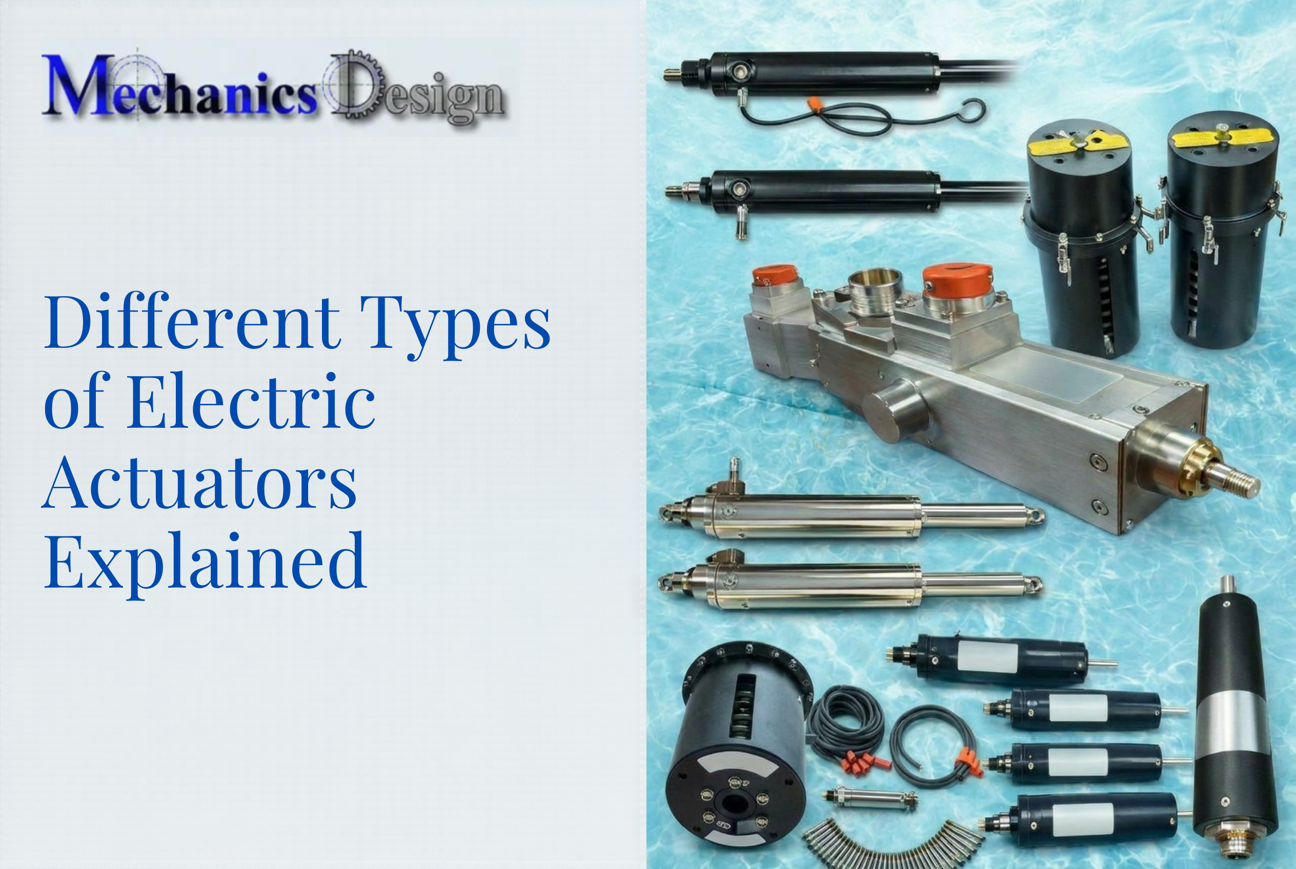
Electric Actuators
How they work: Electric actuators use an electric motor—typically with a worm gear set to reduce speed and multiply torque—to move the valve stem. They accept discrete on/off signals, 4-20mA analog signals, or digital fieldbus protocols and use position feedback (limit switches, encoders, potentiometers) to achieve precise valve positioning.
Best suited for:
- Applications where compressed air or hydraulic infrastructure is unavailable
- Precise modulating control with digital integration (PLCs, DCS, SCADA)
- Remote monitoring and diagnostic requirements
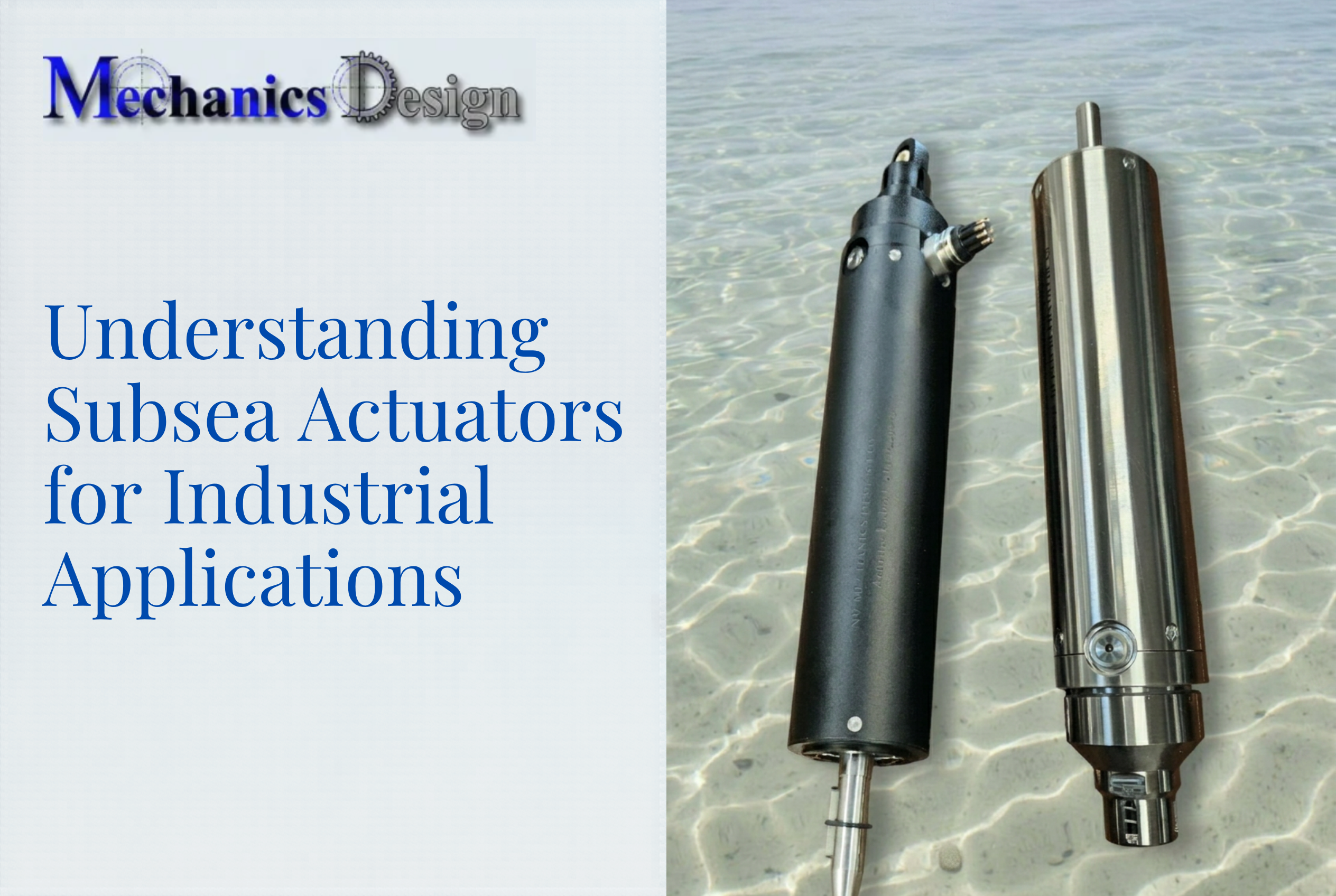
- Specialized environments requiring underwater operation
In subsea environments, electric actuators must be pressure-compensated and depth-rated — standard surface units will not survive. NV Mechanics Design Ltd. builds electric actuators rated to 3,000m water depth, with oil-filled pressure compensation, absolute encoders for position retention between power cycles, and all control circuitry housed within SST 316 or titanium enclosures.
Key strengths:
- Precise positioning (±0.5% accuracy typical)
- Digital control system compatibility with real-time diagnostics
- Programmable travel limits and positioning
- Low maintenance—no air compressor or hydraulic pump required
- Lower lifecycle energy cost in modulating applications
Limitations:
- Slower response than pneumatic or hydraulic (5-60 seconds typical for full stroke)
- Require reliable electrical power supply
- May need battery backup for failsafe positioning
- More expensive upfront cost
- Require certified explosion-proof ratings (ATEX or IECEx) for hazardous areas
Hydraulic Actuators
How they work: Hydraulic actuators use pressurized hydraulic fluid (typically oil) acting on a piston to generate linear thrust or rotary torque. Because oil is nearly incompressible, hydraulic actuators hold valve position very firmly once fluid flow is blocked — this is called hydraulic lock, and it's particularly valuable for large shutoff valves that must stay precisely in position under high line pressure.
Best suited for:
- Large, high-pressure shutoff valves in pipelines
- Power plants requiring high actuation forces
- Heavy industrial applications (steel mills, mining operations)
- Applications requiring enormous force from compact actuator sizes
Key strengths:
- Generate massive actuating forces—2,000 PSI on a 3-inch piston yields over 14,000 lbs of thrust
- Stable, precise positioning due to fluid incompressibility
- Fast response comparable to pneumatic actuators
- Compact design relative to force output
Limitations:
- Require complete fluid power infrastructure (pump, reservoir, tubing, filtration)
- High installation and infrastructure cost
- Leak risks and oil contamination concerns
- Thick-walled tubing required for high pressures
- Less practical than pneumatic for facility-wide deployment
Manual Actuators
How they work: Manual actuators are handwheels, levers, or gear operators that rely entirely on human force to open or close a valve. They provide no automation capability but are often included as override mechanisms on automated valve assemblies (for example, a declutchable handwheel on a pneumatic actuator for use during air failure).
Best suited for:
- Low-frequency operation in accessible locations
- Applications where automation is not required or cost-justified
- Backup override on automated systems
Key strengths:
- Simplicity and low cost
- No dependency on power or infrastructure
- Reliable when maintained properly
Limitations:
- Inability to operate large or high-torque valves quickly
- Unsuitable for remote or hazardous locations
- Risk of operator delays in emergency response situations
- No integration with automated control systems
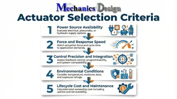
How to Choose the Right Control Valve Actuator
The right actuator type is determined by application requirements—not availability, familiarity, or lowest upfront cost. Evaluating five key factors will guide a reliable decision.
Power source availability is often the most immediate filter. Determine what energy sources exist on-site: compressed air, electrical supply, hydraulic infrastructure, or none. Installing pneumatic actuators without a compressed air system—or electric actuators without reliable power—creates dependencies that simply don't exist.
From there, evaluate these selection criteria:
- Force, torque, and response speed: Size the actuator to handle worst-case pressure differentials with safety margins, as required by ISA-96 and API 6DX standards. For emergency shutdowns or rapid cycling, pneumatic and hydraulic actuators typically respond faster than electric.
- Control precision and system integration: Modulating control applications—where precise intermediate positioning matters—pair best with electric actuators offering analog or fieldbus signal capability. Simple on/off service can use pneumatic or hydraulic types.
- Environmental and operating conditions: Account for ambient temperature range, moisture exposure, corrosion risk, and hazardous atmospheres. Subsea installations add further requirements: depth-rated pressure compensation, sealed enclosures (IP67/IP68 minimum), and materials certified for marine conditions at the target operating depth.
- Long-term cost and maintenance: Purchase price is only part of the equation. Factor in infrastructure costs (compressed air systems, hydraulic power units), energy consumption, and maintenance intervals. Electric actuators generally carry lower ongoing maintenance than hydraulic; pneumatic systems require consistent clean, dry air supply management.
What to Check Before Finalizing Your Actuator Selection
Avoid Over-Specifying
Resist selecting the most advanced or highest-force actuator when a simpler type meets requirements. Over-specification inflates cost without improving performance and adds unnecessary maintenance complexity.
Verify Compatibility Before Ordering
Confirm the following before placing an order, as incompatible specifications discovered during installation create expensive commissioning delays — mismatched ISO 5211 flange combinations are among the most common culprits:
- Mounting interface: Matches EN ISO 5210 (multi-turn) or EN ISO 5211 (part-turn) as required by the valve body
- Output torque or thrust: Sized for the valve's actual operating load, not a generic estimate
- Signal type: Compatible with the site control system (4–20 mA, digital bus, on/off)
Account for Failsafe Requirements
Determine the required fail position — fail-open, fail-close, or fail-in-place — before specifying the actuator. The actuator must include the correct spring-return, battery backup, or hydraulic accumulator to guarantee that position on power or signal loss.
IEC 61508/61511 functional safety standards require evaluating the entire final element assembly — solenoid, actuator, and valve — to meet SIL requirements. Specifying the actuator in isolation is not sufficient.
Don't Select Based on Familiarity Alone
Choosing an actuator type based solely on prior use, rather than current application requirements, routinely causes performance issues. Evaluate each application on its own criteria.
Frequently Asked Questions
What is an actuator control valve?
An actuator control valve is a valve assembly combining a valve body with an actuator—the mechanism (pneumatic, electric, hydraulic, or manual) that physically moves the valve to regulate flow in response to a control signal.
How does an actuator valve work?
The actuator receives an input signal (air pressure, electrical current, hydraulic pressure, or manual force), converts that energy into linear or rotary mechanical movement, and uses that movement to open, close, or partially position the valve trim to control fluid flow.
How much does it cost to replace a valve actuator?
Replacement cost depends on actuator type, valve size, and application. Pneumatic actuators typically run $500–$5,000 USD; electric actuators range from $1,000–$15,000 USD. Installation labor, system downtime, and control system reconfiguration add to the total project cost.
What is the difference between pneumatic and electric actuators?
Pneumatic actuators use compressed air for fast, reliable movement and suit hazardous environments with existing air infrastructure. Electric actuators offer precise positioning and digital integration, though they depend on electrical power and typically respond more slowly.
What is the most common type of control valve actuator?
Pneumatic actuators are the most widely used in industrial process plants. Their speed, spring-return failsafe design, and compatibility with existing compressed air systems make them a natural fit for refineries, water treatment plants, and chemical processing facilities.
Can control valve actuators be used in underwater or submerged environments?
Yes, but they require specialized engineering. Subsea-rated actuators typically incorporate pressure compensation, oil-filled housings, IP68-or-higher enclosures, depth certification, and corrosion-resistant materials like stainless steel or titanium to survive operational conditions.