Introduction
Selecting an underwater linear actuator for robotic systems is far from routine. In a submerged environment, a poorly matched actuator doesn't just underperform—it can fail catastrophically, causing costly downtime, safety hazards, or complete mission failure. Between 2011 and 2018 alone, 1,030 workers died from confined space injuries, with 205 fatalities occurring in tanks and vats. This stark reality accelerates demand for robotic inspection systems that eliminate human entry entirely.
Engineers and operations managers face a genuine balancing act: speed and force output must both be optimized, and neither can be evaluated in isolation from the underwater environment itself. Pressure, corrosion, and sealed electronics add constraints that don't exist in surface applications — and getting the selection wrong directly affects system reliability and operational safety. This guide covers the key factors engineers need to weigh when specifying an actuator for submerged robotic systems.
TL;DR
- Electric underwater linear actuators convert power into controlled linear motion — under pressures that would destroy uncompensated housings
- Speed and force exist in direct trade-off: higher gear ratios boost thrust but cut travel speed
- Pressure-compensated, oil-filled housings are essential — without them, seals fail and electronics flood at depth
- Select by force output, travel speed, stroke length, depth rating, duty cycle, and whether you need position feedback
- Mismatched specs mean stalled actuators or burned motors — always validate against your specific deployment environment
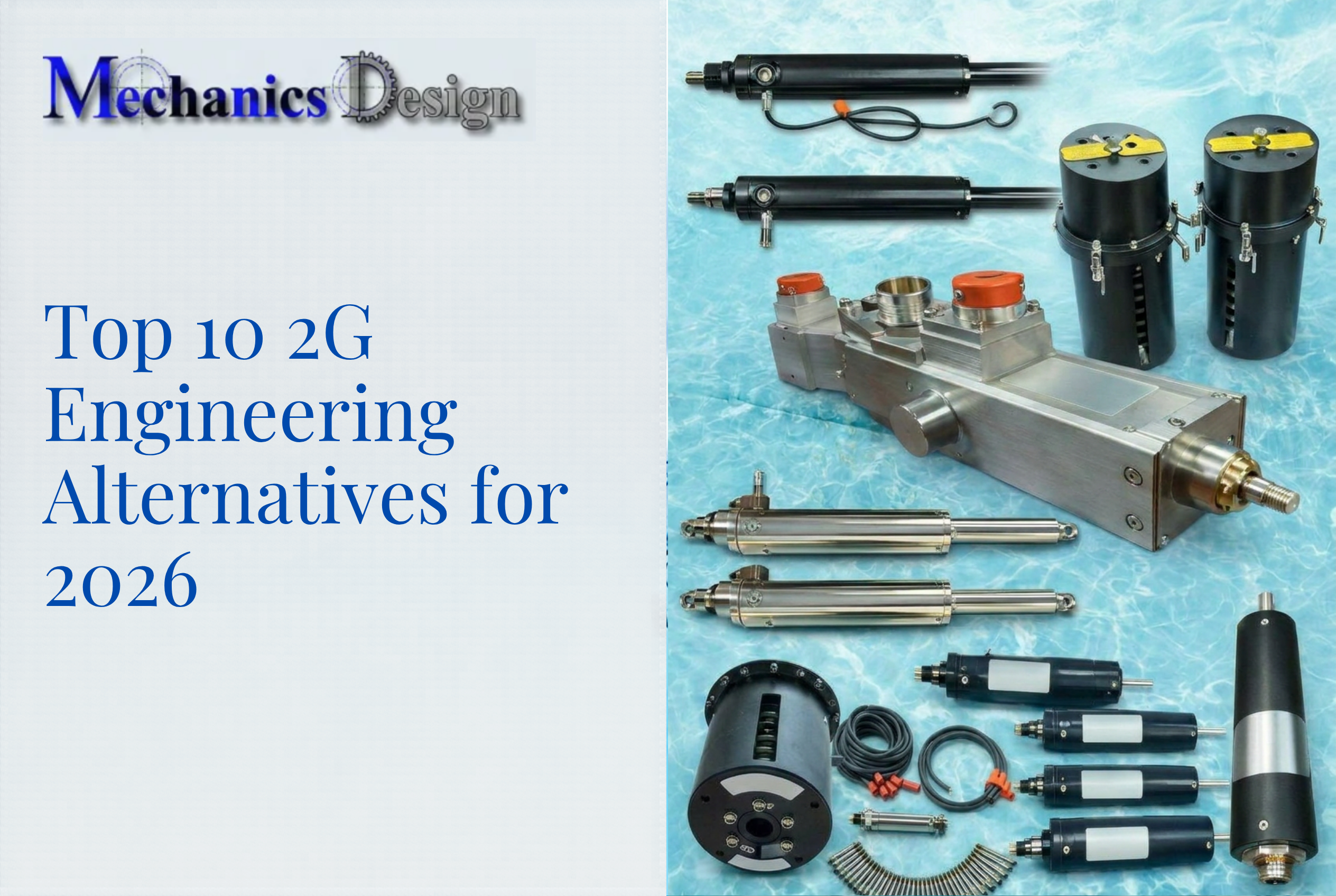
What Is an Underwater Linear Actuator?
An underwater linear actuator is an electrically driven, pressure-compensated device that translates rotational motor torque into precise linear thrust. Unlike standard industrial actuators, these units are purpose-built to operate reliably at significant water depths—often 3,000 meters or more.
Two motion control mechanisms define these actuators: lead-screw-driven designs for high-force precision and self-locking capability, and direct-drive systems for faster actuation with fewer mechanical components. Both add oil-pressure compensation and fully sealed housings to protect electronics and mechanical components from hydrostatic pressure that increases by approximately 1 atmosphere for every 10 meters of depth.
That pressure resistance is what makes these actuators viable for the demanding work they're built to do.
Why Underwater Inspection and Cleaning Operations Rely on Them
Actuators form the mechanical backbone of remotely operated cleaning and inspection robots. They drive brush heads, position cameras, operate grippers, and control buoyancy mechanisms—all without requiring a human diver to enter the tank.
Key operational benefits include:
- Keeps tanks online during cleaning — no draining required
- Removes personnel from confined, hazardous submerged spaces entirely
- Delivers controlled, repeatable motion where manual tools cannot function reliably
- Eliminates the cost of draining thousands of gallons and taking systems offline
Understanding the Speed vs. Force Trade-Off in Underwater Actuators
Every motor has finite power output, governed by the equation P = Force × Velocity. This fundamental physics means speed and force are inversely related—no configuration maximizes both simultaneously.
How the Trade-Off Is Adjusted Mechanically
Gearbox ratio is the primary control lever:
- Higher ratios multiply output force while proportionally reducing travel speed
- Lower ratios increase speed at the expense of thrust capacity
Lead screw pitch provides secondary tuning:
- Finer pitch increases force output but decreases extension rate
- Coarser pitch boosts speed but reduces maximum thrust
Underwater actuators must also factor in added drag from oil-compensated chambers when estimating real-world performance under load.
No-Load vs. Full-Load Speed: A Critical Distinction
Manufacturers typically list no-load speed on datasheets—the maximum speed with zero resistance. Full-load speed—what the actuator actually delivers when moving a mechanism against resistance and water drag—is always lower.
Example from industry data:
| Configuration | No-Load Speed | Full-Load Speed | Max Load |
|---|---|---|---|
| 12V, 20mm pitch, 1:16 ratio | 68 mm/s | 52 mm/s | 500 N |
| 12V, 15mm pitch, 1:67 ratio | 15 mm/s | 9 mm/s | 3,500 N |
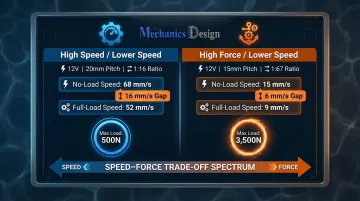
Spec to full-load performance — the no-load figure tells you the ceiling, not the working reality.
Defining Your Working Load
The working load is the force the actuator exerts 90% of the time during operation. Firgelli's linear actuator technical reference recommends specifying roughly 20–25% above the working load as a safety margin.
This buffer accounts for:
- Temperature fluctuations affecting motor performance
- Voltage variations in power supply
- Biofouling drag in wastewater environments
- Peak loads during startup or obstruction contact
Operational Implications for Cleaning and Inspection Robots
In underwater robotics, the speed-force balance has direct mission impact:
- Brush or scrubbing heads need sufficient torque to overcome surface friction and sediment resistance (force priority)
- Camera pan and positioning arms prioritize smooth, controlled sweep speed over maximum thrust
- Valve actuation systems require high force with moderate speed
Getting this balance wrong doesn't just affect performance — it can mean an under-specified actuator stalls under load or an over-specified one sacrifices the positioning precision your application demands. The physics trade-off is fixed; where you land on that curve is the selection decision.
Key Factors to Consider When Choosing an Underwater Linear Actuator
Selecting the wrong actuator specification doesn't just reduce performance—it causes cascading failures in a deployed underwater system. Each parameter below maps directly to a real operational consequence.
Required Force Output
Force output (measured in Newtons or lbf) must account for the total load being moved:
- Mass of the driven mechanism
- Friction coefficients at pivot points or rails
- Water drag on the moving assembly
- Static resistance from sediment or fouling
Sum all forces before comparing against the actuator's rated thrust.
Force requirements vary dramatically by robot function. A tank-cleaning brush drive demands high continuous thrust, while a camera positioning arm may need only moderate force but exceptional repeatability. List every actuator in your system and assign a force requirement to each individually.
Speed Requirements
Speed (typically expressed in mm/s or in/s) governs:
- Cycle time for repetitive operations
- Coverage rate in cleaning applications
- Responsiveness of inspection maneuvering
Too slow: The robot cannot complete its task within the operational window.
Too fast: Positional control becomes imprecise or the actuator overheats under duty cycle limits.
Water resistance adds a real-world speed penalty not captured on dry-bench datasheets. Consult full-load speed curves and prototype-test in the actual medium before finalizing specifications.
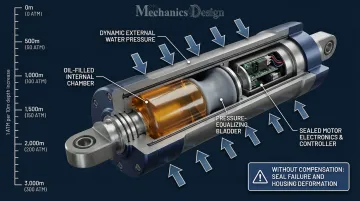
Depth Rating and Pressure Compensation
Water pressure increases by approximately 1 atmosphere for every 10 meters of depth. An actuator without pressure compensation will have seals forced inward or housing deformed, causing immediate failure.
Oil-compensated actuators equalize internal and external pressure using flexible bladders or spring-loaded pistons, protecting electronics and mechanical components at depth. Look for actuators rated to the maximum operating depth of your platform with a meaningful safety margin.
Depth rating isn't just about the actuator housing—cable connectors, sensor ports, and control interfaces must all withstand the same pressure. A system is only as waterproof as its weakest penetration point.
NV Mechanics Design's underwater actuators are pressure-compensated with oil and rated to 3,000 meters water depth—covering the full range of municipal and industrial subsea operations with depth margin to spare.
Stroke Length
Stroke length defines the total range of linear travel an actuator can execute in one direction. It must be matched to the mechanical range of motion required by the specific joint or mechanism being driven.
Too short: The robot cannot complete its intended movement.
Too long: The actuator adds unnecessary bulk and weight to the system.
Measure the full mechanical travel your application requires, then add 10–15% margin to account for mounting tolerances and mechanical flex.
Feedback, Control, and Position Accuracy
In a remotely operated underwater system, operators have no direct tactile or visual feedback from the actuator itself. Position feedback—via encoders, potentiometers, or absolute position sensors—is the only way to confirm a command was executed correctly.
This is critical for:
- Brush positioning that must return to a defined home position
- Camera alignment requiring repeatable angular positioning
- Any repeating motion cycle that depends on accurate position reference
Absolute encoders outperform incremental encoders in underwater applications because they retain position information across power cycles. In deployed ROVs or cleaning robots, power interruptions are common—and an actuator that loses its position reference on restart creates significant operational risk.
NV Mechanics Design's actuators include a 30-bit absolute encoder mounted on the output shaft with position retention between power cycles, eliminating the need for risky subsea homing routines.
Duty Cycle and Thermal Management
Duty cycle is the percentage of time an actuator can run under load before requiring rest to prevent overheating. Underwater cleaning robots often demand sustained operation across multi-hour cleaning cycles, placing heavy duty cycle requirements on actuators.
Exceeding rated duty cycle degrades:
- Motor windings through excessive heat
- Bearing grease through thermal breakdown
- Seal materials through thermal expansion cycles
Match the actuator's continuous duty rating to your actual operating pattern—if your application demands 3-hour cleaning cycles, an actuator rated for 30% duty cycle at 10-minute intervals will fail prematurely.
How NV Mechanics Design's Underwater Linear Actuators Stand Out
NV Mechanics Design is a British Columbia-based robotics technology company focused specifically on underwater inspection and cleaning systems. Their actuator line is built exclusively for submerged environments—not adapted from land-based designs. Purpose-built construction means fewer compromises: tighter housing integration, fewer potential failure points, and specifications matched to real deployment conditions.
Key differentiating specifications:
- Oil pressure compensation rated to 3,000m depth for municipal and industrial deployments
- 30-bit absolute encoder mounted on the output shaft, retaining position data across power cycles
- All circuitry integrated inside the housing — no external electronics required
- Onboard drivers with RS232/RS422 control, reducing cable complexity on long tether runs
- Designed for tank inspection and cleaning platforms with remote operation as standard
Each of those specs targets a specific failure mode that ends deployments early:
- Seal failure under pressure (oil compensation maintains pressure equilibrium)
- Position loss after power interruption (absolute encoder retains position data)
- Control signal degradation through long cable runs (integrated drivers eliminate external electronics)
- Mounting complexity in constrained robot chassis (self-contained design simplifies integration)
When evaluating actuators for municipal water tank robots, cooling tower platforms, or inspection ROVs, ask vendors specifically about encoder type (absolute vs. incremental), where control electronics are housed, and whether depth ratings are pressure-tested or calculated. The answers separate purpose-built systems from adapted ones.
Conclusion
Selecting the right underwater linear actuator means matching every specification to your robot's actual operating environment — depth rating, force, speed, stroke, feedback type, and duty cycle all need to work together, not just look good individually on a datasheet.
Treat each specification as a constraint to satisfy, not a number to maximize. Before evaluating any product, define your requirements for each actuator position:
- Depth rating: Confirm pressure compensation matches your maximum operating depth
- Force and speed: Size to your actual load and cycle time, not theoretical peaks
- Duty cycle: Match to your mission profile to avoid thermal failure mid-operation
- Feedback and control: Verify encoder type and communication protocol fit your system architecture
Revisit these requirements whenever your robot's configuration or deployment conditions change — a spec that worked at 500m may create problems at 2,000m.
Frequently Asked Questions
Frequently Asked Questions
How to choose the right linear actuator?
Start by defining your working load, required speed, and operating environment before evaluating datasheets. Match full-load specifications to application requirements and apply a 20–25% safety margin for real-world variables like temperature fluctuations and biofouling.
What determines the speed of an actuator?
Actuator speed is primarily determined by motor RPM, internal gearbox ratio, and lead screw pitch. Higher gear ratios increase force but reduce speed, and actual operating speed under load will always fall below the no-load figure on the datasheet.
What does stroke mean in actuator?
Stroke is the maximum linear distance the actuator rod can travel in one direction from its fully retracted to fully extended position. Stroke length must be matched to the mechanical range of motion required by your application.
Which type of actuator is best for high force applications?
High-force applications require high gear reduction ratios, robust lead screw designs, and sufficient motor torque. For underwater use, oil-pressure-compensated electric actuators with high thrust ratings are the standard choice.
Can linear actuators be used underwater?
Yes, electric linear actuators can be used underwater when properly sealed and pressure-compensated. Depth rating, corrosion-resistant materials (such as stainless steel 316 or titanium), and oil-filled housings are the key requirements for reliable submerged operation.
What is pressure compensation in an underwater actuator?
Pressure compensation uses oil-filled internal chambers with flexible bladders to equalize pressure between the actuator's interior and the surrounding water. This prevents seal failure and housing deformation at depth, making it essential for any actuator deployed beyond shallow-water conditions.