Introduction
Underwater environments make motor selection a high-stakes decision. Hydrostatic pressure at depth can exceed 600 bar, salt exposure accelerates corrosion on electrical contacts, and any moisture intrusion into rotating components causes rapid failure.
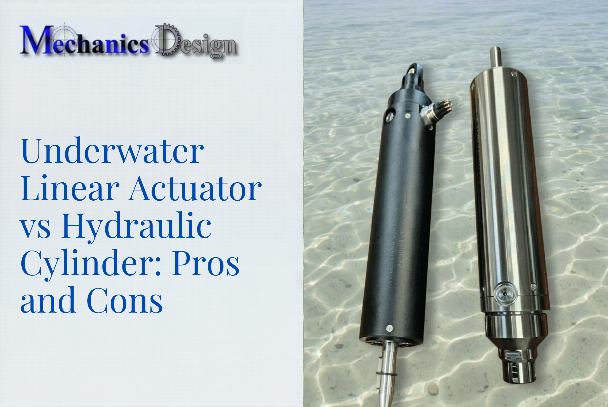
In underwater electric linear actuators, the choice between brushed and brushless DC motors determines not just operational lifespan, but whether deep-sea deployment is viable at all.
This guide explains how brushless DC (BLDC) motors work in underwater linear actuators, why they dominate subsea applications, which technical features matter most for depth capability, and where these actuators are deployed—from ROV manipulator arms to municipal water tank cleaning robots.
TLDR:
- BLDC motors eliminate mechanical brushes, removing the primary failure point in wet, high-pressure environments
- Electronic commutation allows the entire motor to be sealed inside pressure-compensated, oil-filled housings
- Pressure-balanced designs enable operation to 3,000–6,000 meters depth without performance loss
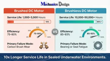
- Service life exceeds 10,000 hours versus 1,000–3,000 hours for brushed motors, where maintenance often means dewatering entire systems
What Is a Brushless DC Linear Actuator?
A brushless DC linear actuator is an electromechanical device that converts electrical energy into controlled push/pull motion. It uses a BLDC motor to spin a lead screw or ball screw, which translates rotation into linear travel—without any physical brush-to-commutator contact inside the motor.
The fundamental difference from brushed actuators: brushed motors rely on carbon brushes pressed against a rotating commutator ring to deliver current to the rotor windings. That mechanical contact is a continuous wear interface. In underwater environments, moisture accelerates oxidation of both components, causing arcing, unpredictable commutation, and premature failure.
Brushless motors eliminate this contact point entirely. An electronic speed controller (ESC) sequences current to the stator windings using rotor position data from Hall effect sensors. With no physical electrical contact between rotating and stationary parts, the motor can be fully sealed inside a waterproof, pressure-compensated housing—the enabling foundation for deep-sea actuator design.
The sealed motor architecture solves the commutation problem, but deploying these actuators subsea introduces additional engineering demands:
- Hydrostatic pressure increasing with depth
- Seawater corrosion attacking housing materials
- Temperature variations affecting seal integrity
- Connector sealing under repeated pressure cycling
Each of these factors shapes how a BLDC actuator is rated, housed, and validated for depth—covered in the sections that follow.
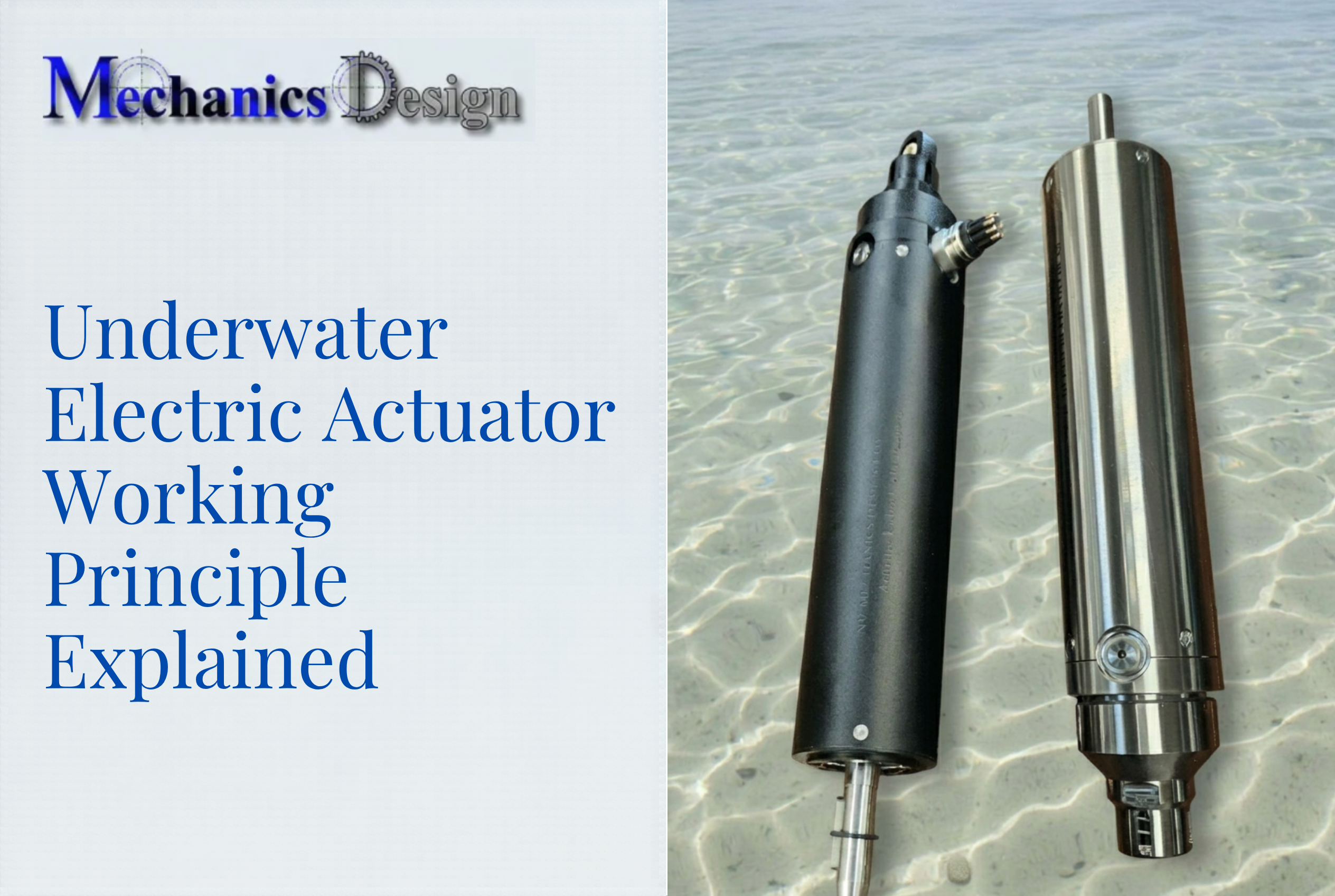
How BLDC Motors Work in Electric Linear Actuators
Stator, Rotor, and Permanent Magnets
The core components are:
- Stator: Outer housing with copper windings arranged in slots along the inner periphery
- Rotor: Inner spinning element embedded with permanent magnets (typically neodymium)
- Electronic speed controller (ESC): Manages current sequencing to the stator windings
The ESC induces sequential magnetic fields in the stator windings that push and pull the rotor's permanent magnets, creating continuous rotation with no physical contact between rotating and stationary parts. This contactless operation generates far less heat than brushed equivalents and allows the motor to be fully enclosed in a sealed housing.
Electronic Commutation and Hall Effect Sensors
Hall effect sensors detect the rotor's exact angular position in real time by sensing the magnetic field of the permanent magnets as they rotate past the sensor. In a typical three-phase BLDC motor, three sensors spaced 120 electrical degrees apart provide a sequence of digital signals representing six possible rotor positions.
The ESC reads these signals and uses them to time stator winding energization precisely — a process called electronic commutation. This closed-loop position awareness lets the motor maintain constant rotational speed as load increases, translating directly to consistent linear force output under variable load conditions.
This matters in underwater operations where current drag, tool resistance, or valve back-pressure can shift unpredictably. Hall sensor-based control also delivers full torque at zero speed — unlike sensorless commutation, which relies on back-EMF voltage that vanishes at low RPM. For subsea valve actuators holding position against pressure, that low-speed torque is non-negotiable.
Key advantages of Hall sensor commutation in subsea actuators:
- Reliable position tracking at any speed, including standstill
- Stable torque output when load fluctuates with depth or flow
- Deterministic commutation timing regardless of back-pressure conditions
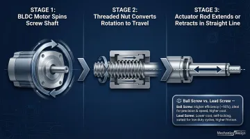
Conversion to Linear Motion
With rotation controlled precisely, the next step is converting that output into straight-line movement. This happens via a lead screw or ball screw mechanism:
- The BLDC motor spins the screw shaft
- A nut threaded onto the screw converts rotation into linear travel
- The nut drives the actuator rod in a straight line
The screw pitch determines the relationship between motor speed and linear travel rate. Ball screws offer higher efficiency and lower friction than lead screws. Lead screws are better suited to high-load, low-duty-cycle applications where efficiency is less critical — ball screws are the standard choice when positioning accuracy and cycle rate matter, as in most subsea robotic deployments.
Why BLDC Motors Are the Preferred Choice for Underwater Linear Actuators
No Mechanical Contact Means Fewer Failure Points in Wet Environments
In a brushed motor, the brush-commutator interface is a continuous mechanical wear point. Research on marine brush-and-slip-ring systems shows that salt spray deposition damages the oxide film on the commutator, promotes electrochemical corrosion, and increases contact resistance. Arcing from unstable commutating currents creates micro-hot spots exceeding copper's melting point, accelerating brush oxidation.
In underwater contexts, moisture ingress into this interface causes:
- Premature carbon brush erosion
- Arcing and electrical shorts
- Accumulation of conductive dust inside sealed housings
- Unpredictable loss of motor control
BLDC motors eliminate this vulnerability entirely. With no brush-commutator contact, the motor's active components can be fully enclosed in a sealed housing—making a waterproof, pressure-resistant design achievable without working around a component that inherently requires a physical electrical path.
Superior Efficiency and Thermal Management at Depth
BLDC motors achieve 85-93% efficiency compared to 75-80% for brushed motors. This efficiency advantage comes from eliminating friction losses at the brush-commutator interface and reducing electrical resistance in the motor windings.
In sealed underwater housings, heat dissipation is limited—water conducts heat away through the housing walls, but excessive internal heat generation shortens seal life and risks motor damage. Lower heat generation from BLDC operation directly extends safe duty cycle in continuous-run applications like ROV thrusters or robotic cleaning systems.
This matters most in battery-powered or tether-limited systems, where every watt determines mission duration. Oceaneering's Momentum Electric ROV uses electric propulsion to reduce power consumption by 45% compared to hydraulic systems, enabling longer missions on the same battery capacity.
Longer Operational Service Life
Service life in underwater equipment is tied directly to maintenance accessibility. In many subsea or tank-installed applications, maintenance requires system shutdown, dewatering, or diver entry—all costly and operationally disruptive.
BLDC motors achieve >10,000 hours MTBF, with many units exceeding 30,000-50,000 hours, compared to 1,000-3,000 hours for brushed motors. The primary failure mode for brushed motors is mechanical abrasion and electrical erosion of carbon brushes.
For BLDC motors in sealed, oil-filled subsea actuators, the limiting factor shifts to mechanical bearing fatigue or seal failure—both of which occur on much longer timescales.
This dramatically extends intervals between required servicing. Avoiding a single unplanned maintenance event—such as draining a municipal water storage tank—can represent substantial cost savings.
The safety case is equally compelling. Between 2011 and 2018, the U.S. Bureau of Labor Statistics recorded 1,030 confined space fatalities, including 205 in tank/bin/vat interiors. Eliminating the need for human entry through reliable remote systems directly reduces safety risk and regulatory compliance burden.
Critical Technical Features of Underwater BLDC Electric Linear Actuators
Pressure Compensation and Housing Sealing
As an actuator descends underwater, ambient water pressure increases approximately 1 bar per 10 meters of depth. At 3,000 meters, external pressure reaches roughly 300 bar (4,350 PSI). Without compensation, this pressure differential would crush standard seals and force water into the housing, destroying electronics and motor windings.
Pressure-Balanced Oil-Filled (PBOF) designs solve this by balancing internal and external pressure through a compliant volume (typically an oil bladder, rolling diaphragm, or piston). The compensator transmits ambient seawater pressure to the internal dielectric fluid, maintaining a slight positive internal pressure (typically 0.7-1 bar) to prevent seawater ingress.
Industry depth rating thresholds:
- Shallow/observation: Up to 300 meters (coastal inspections, offshore wind foundations)
- Mid-water: 300-1,000 meters
- Deep-water/work-class: 1,000-4,000 meters (work-class ROVs)
- Full ocean depth: 6,000-11,000 meters (specialized deep-sea systems)
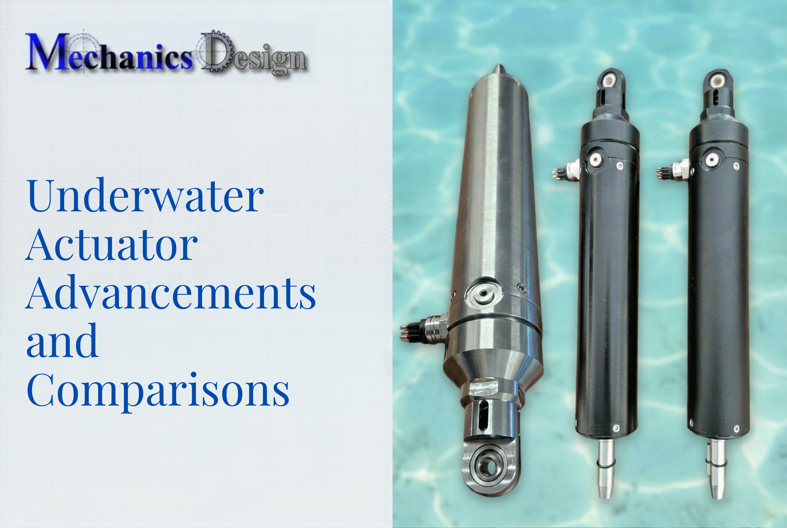
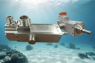
For example, NV Mechanics Design manufactures underwater electric linear actuators that are pressure-compensated with oil and rated to 3,000 meters depth for self-compensated models and 6,000 meters for heavy-duty models. All circuitry is fully enclosed inside the housing—demonstrating how the BLDC's sealed-compatible design enables entirely self-contained units.
The compensator mechanism in these actuators employs a rolling diaphragm design housed within a Delrin construction, paired with stainless steel or Inconel springs to maintain consistent pressure across the full operational volume range. The compensating fluids used are compatible with internal elastomers and electrical components.
Absolute Encoders and Position Feedback
Because operators cannot physically observe actuator position from the surface, reliable position data transmitted via control cable is essential for precise operation of valves, robotic arms, or cleaning heads.
Absolute encoders (as opposed to incremental encoders) retain position data even after a power interruption—critical in systems that may experience temporary power loss at depth. Incremental encoders lose position data upon power failure and require a mechanical homing routine to find a reference mark. This is often impossible for subsea actuators engaged with a load, such as a closed valve or gripped object.
Advanced subsea actuators use dual-loop control architecture: an auxiliary encoder on the motor shaft stabilizes velocity control, while a main absolute encoder on the load ensures zero-backlash positioning. Mounting an encoder solely on the output shaft to eliminate gear backlash causes motor instability because the motor becomes momentarily unloaded during direction changes. The dual-loop approach solves this by maintaining closed-loop control on both the motor and the load.
For PBOF systems, non-contact magnetic ring encoders (e.g., RLS AksIM) are preferred over optical encoders due to their immunity to fluid contamination and high pressure tolerance (rated to 3,000m+). NV Mechanics Design's self-compensated actuators feature a 30-bit absolute encoder mounted on the output shaft, providing 0.1-degree angular resolution and retaining position information between power cycles via non-volatile storage integrated within the encoder itself.
Corrosion-Resistant Materials and Control Integration
Material selection directly determines long-term subsea reliability:
- Titanium (Grade 2/5): Highly corrosion-resistant, used in deepwater housings rated to 6,000-11,000 meters
- 316L stainless steel: Standard for subsea housings, though it requires cathodic protection to prevent crevice corrosion
- Anodized aluminum (6061): Weight-sensitive applications, requires MIL-A-8625 Type III Hardcoat anodizing
Galvanic compatibility is a practical constraint here: aluminum acts as a sacrificial anode when coupled with stainless steel in seawater, causing severe galvanic corrosion unless dissimilar metals are electrically isolated or protected with coatings and sacrificial anodes.
Connector and cable choices must maintain seal integrity under repeated pressure cycling. NV Mechanics Design actuators use Seacon underwater connectors for high-force models and MCBH8M subcon underwater connectors for self-compensated models, both specifically engineered for reliable electrical connections in extreme deep-sea conditions.
Integrated control electronics (drivers, communication protocols such as RS232/RS422) inside the actuator housing eliminate external controller boxes that would require additional waterproof enclosures and cable runs. NV Mechanics Design's self-compensated models feature RS422 (RS485 duplex on 4 wires) communication at 19200 baud, providing reliable, long-distance serial communication with noise immunity critical for underwater environments.
Real-World Applications of Underwater BLDC Electric Linear Actuators
Remotely Operated Vehicles (ROVs) for Underwater Inspection
The global ROV market was valued at USD $3.72 billion in 2026 and is projected to reach USD $6.05 billion by 2031, reflecting massive demand for subsea operations in offshore energy, infrastructure inspection, and scientific research.
BLDC linear actuators control:
- Gripper arms for object manipulation, sample collection, and tool handling
- Camera pan/tilt heads for visual inspection of subsea infrastructure
- Sampling tools for geological or biological specimen retrieval
- Valve actuation on subsea wellheads, pipelines, and process equipment
BLDC motors' quiet operation and precise speed control under variable load are directly relevant to these applications. NV Mechanics Design's Linear Actuator – Self Compensated, for example, delivers 220-330 lbs (1,000-1,500 N) axial force in a compact 2.25" diameter housing — well-suited for space-constrained ROV gripper and manipulation arms. The integrated 30-bit absolute encoder provides RS422/RS232 serial communication with virtual limit switches for travel control, both critical for precise gripper positioning.
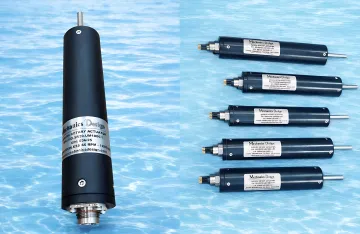
Where heavier loads are involved, the Linear Underwater Actuator Trunion scales from 1,000 N to 77,500 N at 6,000-metre depth ratings, handling deep-sea valve actuation and heavy manipulation tasks.
Underwater Tank and Reservoir Cleaning Robots
Municipal water storage tanks, industrial cooling water reservoirs, and similar facilities require periodic cleaning and inspection. Traditional methods require draining thousands of gallons and sending workers into confined spaces—creating safety hazards and operational disruption.
OSHA 29 CFR 1910.146 mandates strict permit requirements for confined space entry, driving demand for remote robotic cleaning solutions. A 2020 Statistics Canada survey identified approximately one-third of 3,200 assessed Canadian public potable water tanks in less than good physical condition, highlighting the scale of infrastructure maintenance needs.
BLDC linear actuators enable robotic cleaning systems to operate while tanks remain in service, eliminating the need to drain, reducing water loss, and avoiding confined space entry risks. NV Mechanics Design focuses on underwater inspection and cleaning robotics for potable/wastewater tanks and industrial cooling systems, targeting municipal engineering managers and service contractors.
Benefits of keeping tanks online during cleaning:
- Safer: Eliminates diver entry into hazardous confined spaces
- Faster: No drain/refill cycle—tanks remain operational throughout cleaning
- Cheaper: Eliminates water loss (thousands of gallons per tank) and disposal costs
Additional Deployment Environments
Offshore energy infrastructure:
- Valve actuation on subsea wellheads and manifolds
- Pipeline inspection systems
- Riser and mooring tensioner control
Aquaculture facility management:
- Net cleaning and inspection systems
- Feeding system control
- Environmental monitoring equipment positioning
Port and harbor hull cleaning:
- Robotic hull-cleaning systems for biofouling removal
- Underwater structure inspection for bridges and piers
- Propeller and thruster cleaning
Across all these environments, sealed BLDC electric actuators rated to 3,000-6,000 metres offer a clear operational edge over hydraulic systems — no fluid handling infrastructure, fewer seals to fail, and no dedicated power unit required on the vehicle.
Brushless vs. Brushed DC Motors for Underwater Use: Key Differences
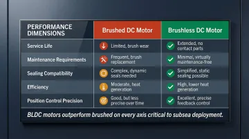
The five dimensions below drive most motor selection decisions for underwater actuator applications. BLDC motors outperform brushed motors on every axis relevant to subsea use.
| Dimension | Brushed DC Motor | Brushless DC Motor |
|---|---|---|
| Service Life | 1,000–3,000 hours (up to 8,000 with premium brushes); limited by carbon brush wear | >10,000 hours MTBF (often 30,000–50,000 hours); limited by bearing or seal failure |
| Maintenance Requirements | Regular brush inspection and replacement; commutator resurfacing | Minimal—no brushes to replace; sealed bearings and electronics |
| Sealing Compatibility | Brush-commutator interface is difficult to seal; moisture intrusion causes rapid failure | Fully sealable—no mechanical contact between rotating and stationary electrical components |
| Efficiency | 75–80%; friction losses at brush contact and higher electrical resistance | 85–93%; no brush friction, lower heat generation, reduced power consumption |
| Position Control Precision | Variable brush contact resistance causes torque ripple and position uncertainty | Electronic commutation with Hall sensor feedback enables precise speed and position control |
These differences become more consequential the deeper and longer a system operates — which is where the following framework applies.
Recommendation Framework
Use brushed motors when:
- Short-duration, intermittent operation (e.g., emergency backup systems)
- Easily accessible for maintenance (surface-mounted equipment)
- Low depth requirements (<100 meters) with simple sealing
- Cost is the primary driver and performance/lifespan are secondary
Use BLDC motors when:
- Regular submersion or continuous underwater operation
- Significant depth (>300 meters) requiring pressure compensation
- Difficult maintenance access (subsea infrastructure, tank-installed systems)
- Long service interval requirements (ROVs, permanent installations)
- Precise position or speed control under variable loads
- Battery-powered or power-limited systems where efficiency matters
In practice, the engineering community has converged on BLDC motors for subsea work — not as a preference, but because the sealing architecture, efficiency margins, and service life requirements leave brushed motors structurally unsuited for the environment.
Frequently Asked Questions
What is a brushless linear actuator?
A brushless linear actuator uses a BLDC motor—which replaces mechanical brush-commutator contact with electronic commutation—to drive a lead or ball screw that converts rotation into linear push/pull motion. The absence of brushes allows the motor to be fully sealed, which is why BLDC designs are standard in underwater and harsh-environment applications.
How are brushless DC motors sealed for underwater use?
BLDC motors in underwater actuators are sealed through a combination of O-ring and face seal housings, pressure-compensated oil-filling to equalize internal and external pressure, and corrosion-resistant materials such as titanium or 316 stainless steel.
What depth can underwater electric linear actuators operate at?
Depth rating depends on housing and pressure-compensation design. High-end commercial underwater linear actuators using oil-filled, pressure-compensated housings can be rated to depths of 3,000 meters for mid-range models and up to 6,000 meters for heavy-duty units.
Why is pressure compensation important for underwater linear actuators?
Without pressure compensation, increasing depth pressure overwhelms standard seals and forces water into the motor housing. Oil-filled cavities with a compliant element—such as a rolling diaphragm or bladder—equalize internal and external pressure, so seals only need to prevent oil/water mixing rather than resist the full ambient pressure differential.
What is the role of Hall effect sensors in a brushless DC motor?
Hall effect sensors detect the rotor's angular position in real time and relay it to the electronic speed controller, which sequences stator winding energization accordingly. This keeps speed and torque consistent under variable loads—critical in underwater actuators where current drag, valve back-pressure, or tool loading can shift unpredictably.